I have already experimented with making the screen monochrome, however, due to lack of resources (dead screens) I abandoned the idea. The second way is to tune the light source. You can already buy LED lamp replacement, but what hobby would it be if just bought everything? Also, their parameters are not as good as my aims.
One disclaimer – the whole build was performed during the lockdown period during COIVD-19 outbreak, so many manufacturing and supply options were limited. Therefore, some of the approaches presented in this post are rather hacky and I would make them differently during normal times.
I decided to build a 7×4 LED array. The reason for going for such a high number of LEDs is to limit their radiation cone – the goal is to produce as parallel rays as possible. With fewer LEDs, I would need a wider cone. When you have rays under an angle, it leads to a side exposure and imprecisions in the print. I used LG6565 – 10W LEDs which emit peak wavelength 405nm. That’s 240 W. Original Mars is roughly 30 W.
I created a simple PCB. I used copper-clad with an aluminium substrate to provide better cooling. Normally, I would buy sodium persulfate and etch the board. However, during COVID outbreak all the drug stores were closed so I just cut the board with an X-acto knife and peeled the excessive copper. Soldering the LEDs on the aluminum substrate was not an option and reflow oven was out of the reach – so I just cut pieces of solder wire, put them on the PCB, put some flux on it, and put it on a gas stove on a thick piece of steel. After 2 minutes, the solder melted, the LEDs nicely arranged. After attaching some wires, the PCB was ready. To improve the cooling I also mounted a beefy heatsink to the backside of the PCB and I added two 60 mm quiet fans.
To drive the LEDs, I decided to go with a separate power supply. I used a switching boost constant-current DC/DC converter bought on Aliexpress. I decided to power it from 24 V to make it as efficient as possible. I added a MOSFET for switching the LEDs. To make things simple, I attached wire on the gate of the original on-board MOSFET for LED switching. One note – the LED array is really bright! There was also a lot of heat coming out of it – but not the excessive heat in the heatsink – the blue light itself carries a lot of energy and you could feel warm even when you put your hand nearly meter from it.
Drawing the PCB layout by hand
I didn't have single clad large enough, so the final panel is composed out of two pices
COVID outbreak = no chemicals available. Trying to make PCB by cutting the pattern
Cutting the PCB and peeling the copper is surprisingly easy
magnetic encoders – small, wonderful resolution, not so fast and expensive
etc.
With two projects in my mind (one really up budget, the second one requiring really small and really fast (>100kHz) encoders) I thought: why not to build a capacitive encoder? Basically a variable capacitor whose capacitance determines the position. It could be cheap (etched on a PCB) and really fast. So I decided to explore possibilities of this approach.
Overview
As usual, I started with an overview of existing solutions. Surprisingly, it is hard to find any reasonable resources. I found only two types of existing projects – professional solutions without any documentation for scientific purposes and a really nasty hobby projects which are far-far away from any reasonable results. There was only one exception – Elm Chan’s laser projector, which uses a capacitive encoder for galvanometer feedback.
In his project, he uses a diode bridge and a high frequency AC voltage (>8 MHz) to measure a capacity difference of two capacitors. The circuit should produce a small voltage on a output proportional to the difference. However, I wasn’t able to reproduce his results. My circuit produced a lot of noise and was practically useless. Clearly I am not an analog guy. So I decided to do it in more digital way.
First prototype
The idea is simple – I create a plate capacitor with half-circle electrodes by etching a pattern on main PCB and on a small PCB carried by motor shaft. Then I use the 555 timer in an astable configuration with the plate capacitor for timing. The circuit will produce a square-wave signal with a period proportional to the overlap of the electrodes and therefore, proportional to the shaft position. The frequency can be measured using a timer on a MCU in the input-capture mode. Simple, right?
First prototype of capacitive encoder
After designing a simple PCB, which you can find here, I etched it and populated it. To protect the electrodes from a short and also to create as small spacing as possible (to increase capacity) I covered one of the electrodes with a transparent tape. The diameter of the semicircles is 15 mm (and therefore the active area is roughly 88 mm2. Based on resistor values I used, and the frequency I obtained, the capacity of this capacitor is about 8 pF – 5 times more then I expected (the tape is probably a better dielectric then I expected).
The first tests looked promising – I was able to measure a position, however the whole system was quite noisy and especially sensitive to touch – and mechanical stress. This is probably due to movement of the plates – event they lie on a the tape, if you squeeze them a little, they move closer together and it leads to big increase in the capacity. I also think this setup is quite sensitive to air humidity and temperature. Also it does not allow for continuous rotation because of the wire connecting one electrode to the main PCB. I was thinking about connecting the the other electrode via the motor shaft and the motor case, however, one of my friends had a nice idea (thanks Jiří).
Second prototype
The idea behind second prototype is quite simple – do not move the electrodes, move with a semi-circle of a good dielectric material between two fixed plates. The electrodes are fixed and therefore it is easier to maintain a fixed distance between them. Also, even if the dielectric semicircle does not maintain a constant distance from the electrodes, it makes no difference as the ratio of air and dielectric is the same (and that’s what affects the capacity). For the material I used FR-4 – it is easy to get and has 4 times bigger dielectric constant than air.
Second prototype
Second prototype
I also tried to make two electrodes for the second prototype to get rid of humidity and temperature dependency – I wanted to measure a capacity difference by measuring two capacities and making the compensation in MCU. However it wasn’t a good idea to put the two 555 timers on the other sides of PCB. Even with a decent battery of capacitors, they interfered in their function and produced an instability in the oscillation.
The other side of PCB with a ground plane and without the second 555 timer
When I got rid of one of the second timer and also introduced a ground plane on the other side of the circular electrodes I was surprised with results. To test the capacitor I used ESP32 with a motor control timer in the input capture mode. This timer’s clock tick at 80 MHz and feature a 32 bit counter. First, I arranged the resistors of the 555 timer to get a frequency around 100 kHz (I was aming for really fast encoders). With this setup, the timer makes roughly 800 ticks per period. As the capacitor still has a capacity even when there is no dielectric, the low period was 720 tics and the high period was 860 period – i.e. I got resolution of 140 positions. When the encoder is stable, there is a surprisingly small noise – only +-1 tick. Also I let the encoder run for over two hours and there was no drift in the position. You might think – 140 positions isn’t much, but I can read it at 100 kHz! When I lower the frequency (or if I could get the timers in ESP32 to tick faster) I am able to increase the resolution. So basically it is a trade off between speed and resolution.
What about continuous rotation?
If you read carefully and think a little, there is one small glitch in my setup – I am only able to detect position in the range 0-180° and no more. If I continue the movement above this range, I am not able to tell if I continue or if I am returning back as the capacity decreases the same way on the both sides. There is however a simple solution, which I unfortunately haven’t tested yet.
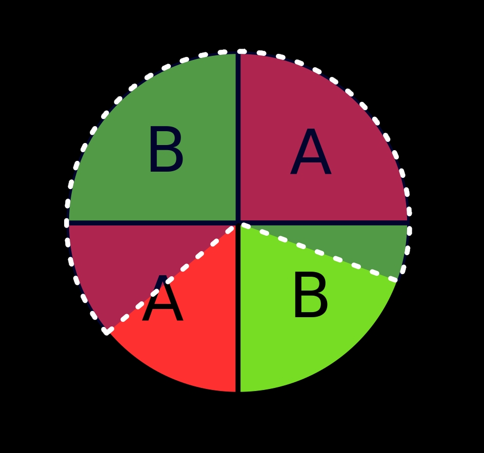
Electrode pattern
You need two electrodes A and B and a dielectric disk taking 2/3 of the full circle (semi transparent in the image). In this configuration you can always tell in which direction you move.
Conclusion
I would call my work as “proof-of-concept”. I think ultra fast capacitive encoders are feasible if you can measure period fast enough or you make Elm Chan’s circuit to work and use ADC instead. The capacitive encoder can be also a dirty-cheap solution – you need only a space on PCB, two 555 timer, 4 resistors and 4 capacitors. As the capacity of my plate capacitor is roughly 10 pF I think you could reduce its size 2 or 3 times and still get reliable results so not much of a space is necessary.
But always remember – time is money and an “expensive” solution in a form of a magnetic encoder IC might be in the end the cheapest solution.
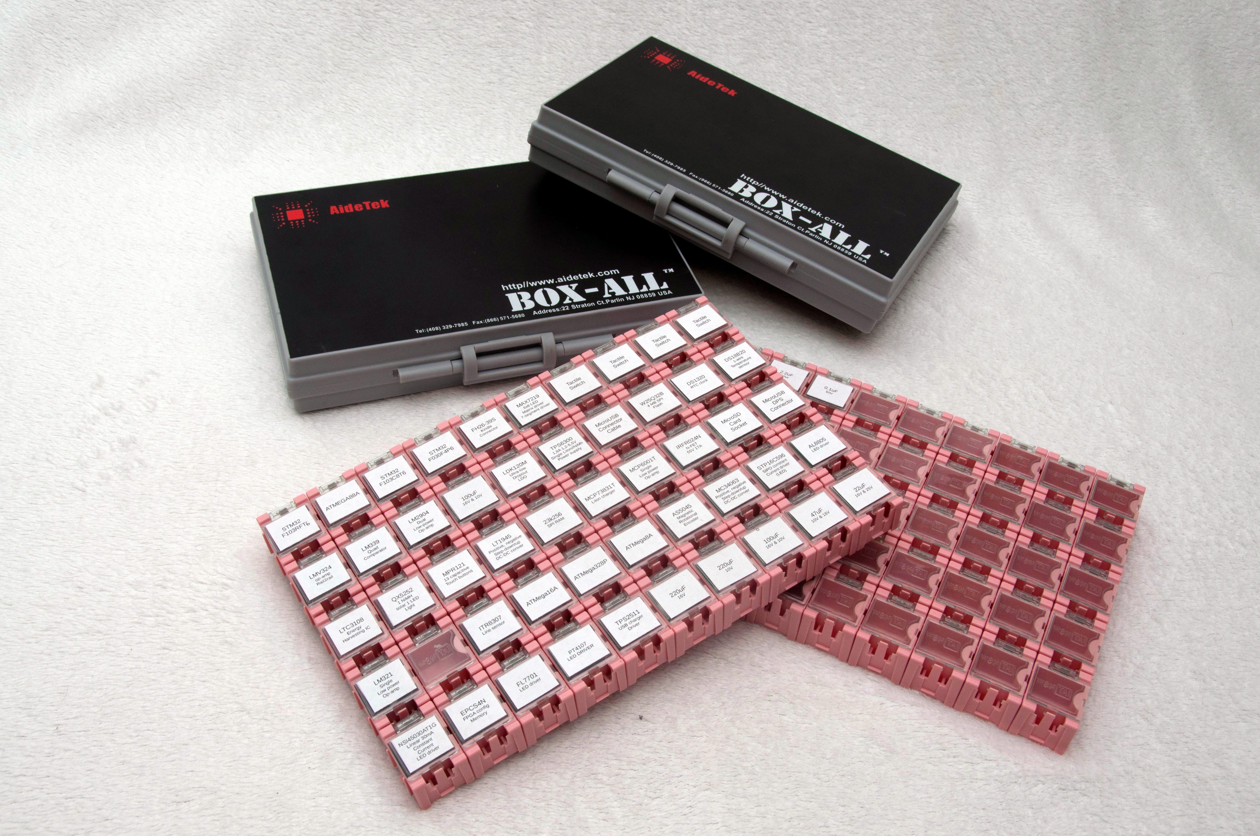
In my previous article I briefly showed the way I store and organize my SMD components. Even it is way better than storing parts in labeled plastic bags, in which the parts are usually shipped, it is still far away from being perfect. I was already looking for a better solution for a six months or so, when I finally found two products, which seemed like a possible solution – Aidetek Box-All Cases and WenTai Boxes.
I use SMD components in my projects whenever it is possible. I like when things are compact, look professional and also I hate drilling PCBs. Also many modern components aren’t available in other packages. However with bright sides of SMD components comes the dark side — the storage.
You need several hundreds type of components to do something meaningful. The components are small, come in similar packages usually with no labeling (capacitors, inductors, SOT, QFN — all of them have no, or at least not fully descriptive label). Putting them in a one large bag isn’t a good idea. Once you loose track what kind of component is it, you can throw it out. Sometimes it can be measured, but usually the time doesn’t worth the money.
I used to keep my components in the original carrier tape, usually with a handwritten label. All the tapes were in several plastic bags. After my collection of components grew up a little bit, this kind of storage was unusable. Lookup a component of a particular type was time consuming, reading small, often blurred hand-written labels, was a pain. Maybe you know it by yourself.
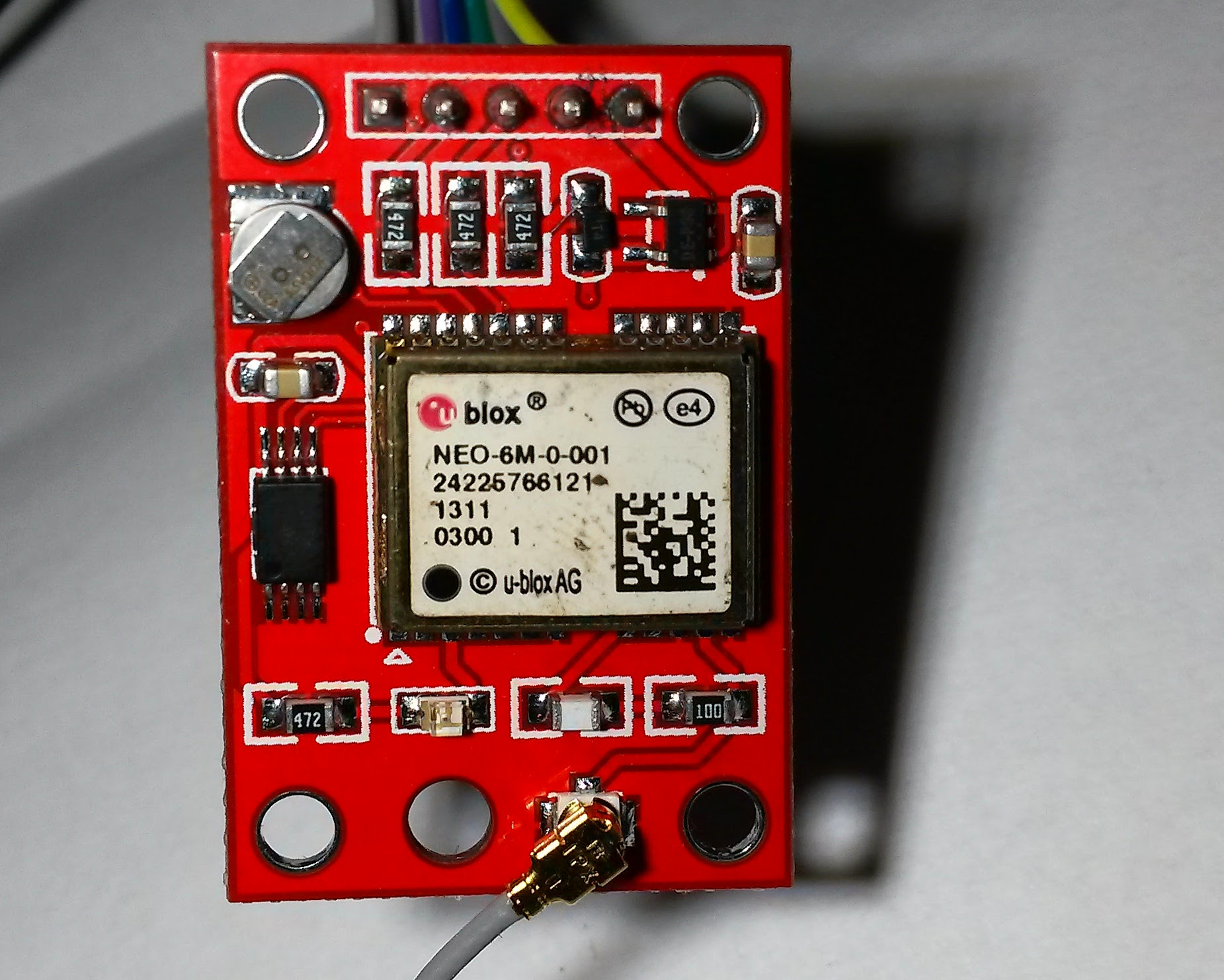
GPS is a really nice and quite cheap technology – unless you want accuracy in orders of decimeters or centimeters. Yes, there are high-accuracy GPS receivers which can achieve such an accuracy, however the price of the cheapest one is starting at $500. Not really a something a hobbyist can afford/is willing to pay for.
For many application there’s no need for absolute position, a relative position of 2 or more GPS receivers is sufficient. Take an autonomous robot moving in outside area as an example. You can setup a fixed ground station and navigate it relative to it. The intuition tells you that measuring relative position should be more accurate (when we’re talking about station less than 500 m away from each other) that measuring the absolute position int the WGS-84 system.
Why? The most of the GPS receiver’s accuracy depends on the atmospheric delay (the time the GPS signal travels through air) and it should be pretty much-less the same in a small ground area. So, having two the same GPS receivers, which uses the same antennas and algorithms for position measurement, should produce the same results, right? Well, kinda.
There are many papers out there about relative GPS position measurements. I’ve read several of them and none of them and I have to say they were bad. All of them were very shallow with lots of motivation and no results (don’t even think about public implementation!). I gave up reading (for now).
Almost daily I come to problems I’ve seen before. Usually I have solved them successfully, but I struggle to remember the correct and effective solution when I need it again. I have also created lots of gadgets and devices, which usually after some time end up stacked in a box. And no one, even myself, think of them again. I think it’s a pity.
This is why I decided to start this blog, called “mind.dump()” – to make a dump of my mind, thoughts, ideas and experiences. To archive them, make them searchable and also to share them. I profit a lot from others’ experiences, they shared, in my work, so I think it’s right to do the same and possibly to help others.
Expect posts about programming, electronic, computer science, robotics, CNC machining and others.