ESP-12 modules are great for integration to custom product as they fit nice on a PCB. However the prototyping process can be painful due to the incompatibility with standard 2.5 mm pin headers. You can use a full development board like NodeMCU with all its imperfections (size, high current consumption1 compared to ESP sleep states, mismatched pin names 2, etc.) or you can take a soldering iron, wire and do all the necessary wiring as a “3D post-modern artistic piece from a copper wire”. To remind; ESP8266 requires several GPIO pins to be pulled-up or pulled-down in order to boot from flash memory or to enter a bootloder (see ESP8266 Wiki for details), so a little bit of wiring is unavoidable. In some cases you might want to attach a voltage regulator.
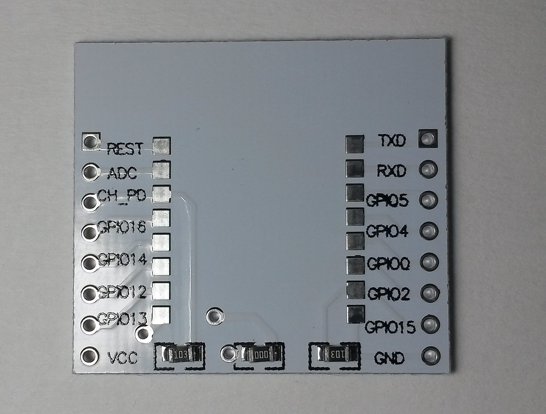
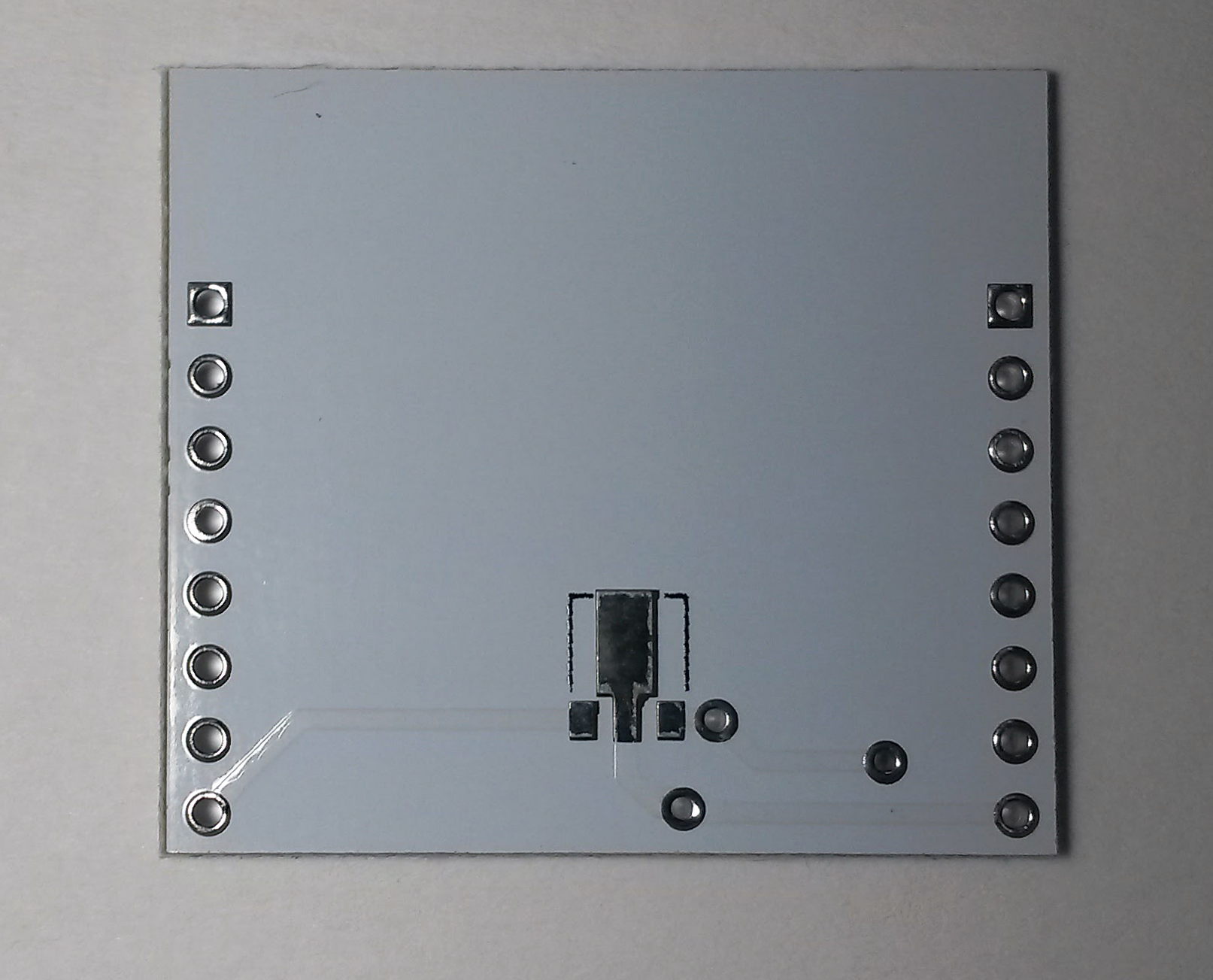
Few weeks ago I found a pack of 10 minimal ESP8266 breakout boards for a $1.3 on AliExpress (pin headers included). As I am a fan of minimal developments boards I gave it a try. The boards are compatible with ESP-7/8/12 modules. As you can see in the pictures, they provide several pull-up/downs and a place for a voltage regulator. From the sellers description and poor quality photos, the board connections was unclear, but three resistors suggested it might be prepared for flash booting. Also there was no photo of the bottom side of the board.
When the boards arrived, I was disappointed – there is a pull-up on CH_PD (enable) pin and pull-down on GPIO15. The third resistor is a 0R connection bridging the SOT-89 voltage regulator on the other side. So users can choose, if they want a direct VCC connection, or use a regulator. This however means, that you need to connect RESET and GPIO2 to successfully boot or flash the ESP. I would appreciate the pull-up on GPIO2, as I usually use OTA update and therefore I need to flash ESP using UART just for the first time.
The regulator pinout was also a surprise for me. I am used to the common layout (from left) Gnd, Vout, Vin and I thought there is no other. However there are regulator with switched Vin and Vout. This board features this (at least for me) unusual pinout. I would also appreciate a universal footprint, which can be used for both SOT-89 and SOT-223 (as my home supplies feature a lot of AMS1117).
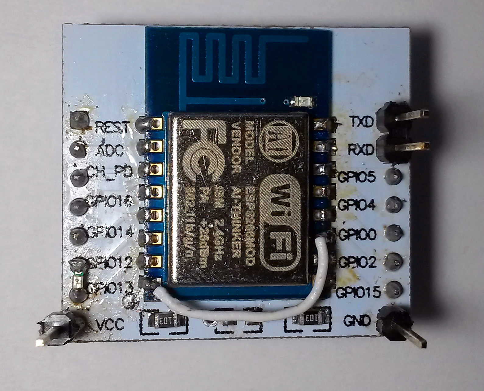
For my latest project I needed a wireless UART, so I decided to use ESP8266. However I didn’t have any development board at home, so I decided to try this minimal breakout board. After 10 minutes of soldering I had a working board – even with AMS1117 regulator. Only a little bit of kapton tape to prevent a shortcut on vias, two 0603 resistors, one 0603 LED and 2 pieces of wire were needed to make it work. The result isn’t beautiful, but it serves its purpose (and is much more durable and usable than direct wiring).
To conclude; even I was disappointed when the boards arrived, after the first usage I changed my mind. They aren’t perfect, but for the $0.13 per piece they serve theirs purpose – to ease your life, when you are doing quick prototypes with ESP, where you need relatively small size or a freedom, when it comes to the wiring.
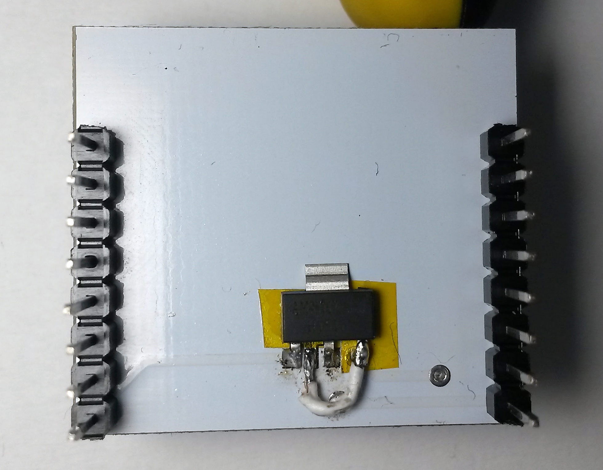
Soldering SOT-223 regulator on a SOT-89 footprint with swapped Vin and Vout pins. Nothing a kapton tape over vias and a piece of wire couldn’t solve
Recent news: My open letter to the 3D-printing community
I love the 3D-printing community, but I think there is room for improvement. Let's get better in 2023! Read the full letter.
Support my work!
If you like my work (these blog posts, my software and CAD models) and you would like to see more posts on various topics coming, consider supporting me in various ways:
- You can become my sponsor on Github.
- If you prefer, you can also become my Patreon.
- You can buy me a coffee on Ko-fi,
- or you can buy something from my Tindie store (also see below),
- Or you can just share my work!
If you are interested in knowing what I am up to and recent sneak-peaks, consider following me on social media (Twitter, Instagram, Facebook).
My store offers
I launched new tank cleaning kits for Elegoo Saturn, Saturn S, Mars 1, and Mars 3. You can find them in my store.
Related Posts
- See this blog post about NodeMCU power consumption
- NodeMCU vs. ESP8266 pin names
Hello,
I’m vey interested in your article “Cheap Minimal ESP8266 ESP-7/812 Breakout Board” since I have the same components.
I see the need for the wire to pull-up GPIO2 but I don’t understand why there is a 0603 resistor between GPIO12 and GPIO13.
Could you explain the reason?
Thanks in advance
Hi,
it is not a resistor, it is a 0603 LED, which I attached as a dirty-hack. I needed a signalisation for my project, so I attached a LED between GPIO12 an 13. One pin acts as a ground and second one acts as a switch.
Hi, great work in there! 🙂 But are you sure that you have everything connected? What about REST? It should be HIGH? And what about if you wanna use deep-sleep? Can you make some update about this please? I am currently working with this board, but have some problems running it correctly 🙁 Thanks for a help! 🙂
Hi, unfortunately I haven’t tested this board with deep sleep, so I am afraid I am not able to help.
There is a similar board available on ebay which has the proper pads for the AM1117. It may not have been available when you bought yours.