After publishing yesterday’s post I observed a strange thing – the lid of my Elegoo Mars came off during printing. The encoder I mounted on top of the Z-axis bounced it off. That was strange, how? And then it hit me. I have never, ever measured backlash of the bearings of the lead screw. I have only measured the backlash of the screw itself. Well, I think a video is worth more than a thousand words:
There is a play roughly 2 mm in the housing of the lead screw! I disassembled the printer:
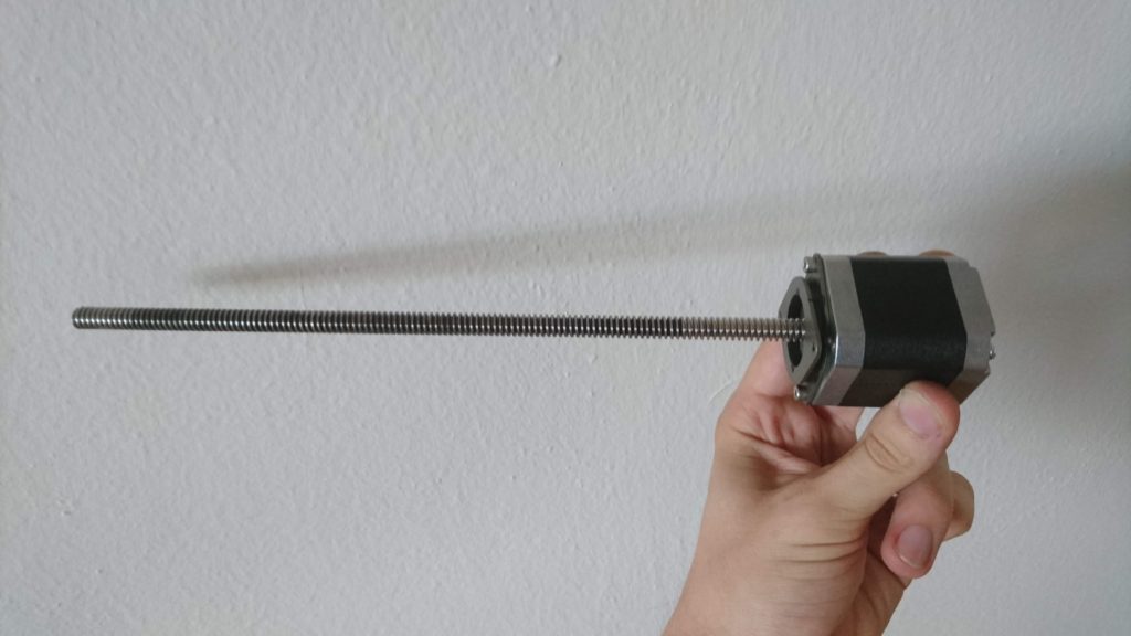
The screw servers as the shaft of the motor. 
The motor is mounted on a silent block. 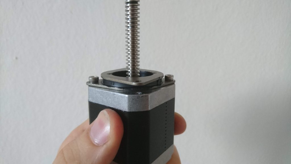
See that the essential part of the silent block is a rubber. 
The silent block 
Motor caption 
Bearing on the back side of the motor 
Spacer below the bearing 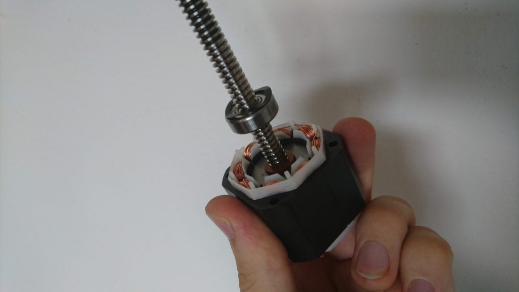
Bearing on the bottom side of the motor – see the spring washer
The cause is clear – even the motor has a lead screw as shaft and therefore, you would assume it is designed for axial load, it is not. There are ordinary ball bearings (no axial nor angle contact bearings) and most importantly – there is a spring washer tensioning the bearings – just like in an ordinary stepper designed for purely radial load. This is, in my opinion, a clear failure of the motor manufacturer MOCOC TECH. Also, there is another source of problems – the silencer – as the screw is mounted in the motor and the rubber silencer is soft. The silencer probably prevents from resonating with the top plate of the printer and also creates a flexible element which can compensate for the axial misalignment of the screw and the nut.
When you combine this flexible play in the screw with my observation about forces present during printing, you get imprecise print height – up to the size of the play of the screw. It can shrink or squeeze your layers arbitrarily.
What is the solution? There are three solutions in my mind:
- dirty & cheap – get two M8 washers, put them in the motor’s rotor, remove the spring washer and tightened motor body screws carefully to slightly tension the ball bearings. Also, remove the silent block. This is a solution for roughly 3 CZK. Warning: This is a dirty solution. Deep groove ball bearings are not designed for axial load nor tensioning. Also by removing the silent block, you remove flexible element which could compensate for misalignment of the screw and the nut. Your risk shorter life of the bearing, screw, and nut. On the other hand, the speeds and axial loads on Elegoo Mars are not that big, so you might be OK for years with this solution.
- better solution – get a pair of axial bearings F8-19G and use them instead of the ball bearing. Pretention them either as in the previous case or with a hard spring washer.
- The best solution – build separate housing for the screw with contact angle bearings and connect the motor via flexible shaft coupler. This solution provides noise reduction using the silencer. However, when you try this it might be worth it to rebuild the Z-axis to use a linear rail as the Elegoo solution of the Z-axis has a high effect-to-cost ratio, however, I can measure about 0.2 mm of play when I apply reasonable forces by hand.
As the G8-19G bearings are not available at my local store and I had to order them, I applied the dirty & cheap fix to find out what improvement can I get. Spoiler: a huge one.
I printed the test pieces from my previous posts (volume 1, volume 3, volume 4) and the problem practically disappeared. Compare the real size of the test piece before and after:
The full dataset can be found in this table (new measurements are from sample 10).
Most notably what changed is that if an error is introduced in a layer, it is compensated by the others. Therefore absolute precision is preserved. See that all the test pieces got practically the same height.
If you look at test piece 11, you’ll see it is quite distorted. It is the sample surrounded by a full plate of material. There was noticeable distortion, however, it was different compared to the previous cases. The overall test piece height was preserved, but the layers surrounded by material were a little bit higher. Just like first layers of other pieces. This is probably due to the effect I described in volume 4 (recommend reading before continuing). The effect is that the resin is viscous and as the build plate sinks, it has to push away the resin. When I introduced the delay to allow the resin to flow away and to settle the build plate in place I got much more precise pieces. On the simple pieces, even the first layers got the correct height. On the pieces with extra material, the distortion is still there, however it is much less significant. I believe by introducing even longer delay, we can get much more precise (I plan to do this experiment).

Perfect test samples.
What struggles me is that instead of 3 mm I got 2.9 mm – pretty constantly. Therefore, I printed another staircase – 0.5 mm steps, 15 mm in total height (sample 15). I also got less – 14.7 mm. Currently, I have no idea what is this caused by – it not a constant error (not coming from incorrect bed leveling) and it is too large for shrinkage (2 % – epoxy or polyurethane resins have shrinkage less than 0.5 % and I don’t expect printer resin to be that different). Maybe tensioned bearings with misaligned screws cause step loses on the stepper. I am also not sure the error is linear – I’ll have to run many more tests. Any ideas what could it be caused by?
On the topic of lost steps – before the first print I releveled the build plate. When the print started, the build platform started to move down as expected. The build plate touched the bottom of the VAT and the stepper still continued – by the sound it clearly lost some steps. I am sure I have leveled my bed correctly. I leveled it against empty VAT. Is it possible the printer FW moves the platform a little bit below the zero point to pretention the Z-Axis to mitigate the problem with flexible housing of the screw? I don’t know, but this also something I would like to explore in the future.
After all, even there are still open questions I consider my Elegoo Mars to be used as I intended when buying it – to produce precise functional mechanical components.
Recent news: My open letter to the 3D-printing community
I love the 3D-printing community, but I think there is room for improvement. Let's get better in 2023! Read the full letter.
Support my work!
If you like my work (these blog posts, my software and CAD models) and you would like to see more posts on various topics coming, consider supporting me in various ways:
- You can become my sponsor on Github.
- If you prefer, you can also become my Patreon.
- You can buy me a coffee on Ko-fi,
- or you can buy something from my Tindie store (also see below),
- Or you can just share my work!
If you are interested in knowing what I am up to and recent sneak-peaks, consider following me on social media (Twitter, Instagram, Facebook).
My store offers
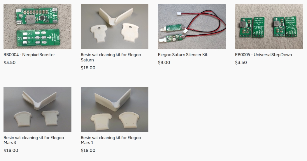
I launched new tank cleaning kits for Elegoo Saturn, Saturn S, Mars 1, and Mars 3. You can find them in my store.
Hi Jan!
First of all incredible research!
Just a pair of simple question about the dirty solution.
When you remove the silent block, does the 2 m8 washer substitute it’s space?
And second, you say you tried it, can you post a photo of the solution?
Thanks!!
Yes, they do. I removed the spring washer and one of the grey spacers. Then I put 2 M8 washer to the bottom (below the thin spacers) and to the top (also below the thin spacers).
You’re SUUUPER right! The motor is set up so that it bears load moving in the +Z direction, like when peeling the print off the FEP. But the spring washer crushes in the -Z direction, when homing – the slightest bit of resin viscosity results in a false home, LOWER than true Z=0, and which can’t be rectified by re-leveling the bed because it happens at the beginning of each print. This also explains why I got over-thick results in my own testing when I provided manual down-force on the knob when starting the print.
Just about to crack mine open and remove the spring washer.
Nice findings! Could this problem also be solved without disassembling the motor housing? For example you could drill a hole in the top Z axis cover (the aluminium plate on top of the linear rails), tap a m3 thread in and put a screw in from the top. Screw it in so it just slightly touches the center of the lead screw. That way the lead screw can neither move up nor down when under load. Just a quick idea.
I do think that would work, but it’d also be pretty error prone. Without using a thrust bearing there, it’ll mean the motor encounters a bunch of resistance when it hits the stop, which could cause skipped steps. It’ll also be pushing into the screw while rotating, which will have a tendency to try to move the screw in height, slowly undoing your work over time. Less effort and probably better outcome, 3D print a clip that fits over the metal, and has a well-tuned thickness on the bottom. Same problem with force and possibly skipped steps, but at least it doesn’t require drilling and tapping.
Jan,
good work finding the backlash problem. Noticed the problem in my printer too. Manifesting itself as steps on what should be flat surfaces. Could you give a link to where you got the thrust bearings from?
BTW. regarding the resin shrinkage, I’d say 2% linear is pretty good for an acrylate/ methacrylate system. Vinyl monomers shrink more on polymerization than do epoxies. A trick used to get down to the 2% you witnessed is to partially polymerise on of the monomeric components and then dissolve these in another monomer. (Thick acrylic sheets are formed by dissolving polymethyl methacrylate in methyl methacrylate, for example- so-called prepolymer method) Of Course, the polymer formed must be soluble in its own monomer (this is not always the case).
Different resins from different makers might vary but once you know how much shrinkage a particular resin gives, just factor this into your design. X,y and Z should all be same. If you are really fussy, you should also keep resin at a uniform temperature, as you will see some thermal shrinkage as polymerised resin cools down.
I think the shrinkage is not that big as I get quite consistent dimensions of my prints in the XY direction. From my latest print experiments, it seems like the error is linear (roughly 0.5 %). I plan to measure the screw to find out if it is true or not.
The is offset by light bleed from the mSLA filter screen and is dependant an the construction of the printer. This results in an increase in dimensions in the xy plane, as the light bleed is more or less a fixed figure with the latest LED matrix panels and polarising filters across the entire area of the filter screen, where as the shrinkage is a percentage, it is possible to print a square exactly the correct shape.
Thanks for the thorough measurement work, it saved me a lot of time.
Spoiler first: I achieved a little under 1% linear Z error in the end (I need to get a measuring screw to be certain how much below 1%, the calipers are no real help here anymore). Here’s what I found worked and what didn’t.
I tried out Jan’s ‘better solution’ variant with a couple of F8-19G axial bearings and some custom height washers. While this approach does fix the lost 1.5mm of layers, it causes new severe problems. The axial bearings provide almost no radial guidance for the motor shaft, so the rotor tumbles slightly inside the stator. At the top of the lead screw, this can be seen as 3-4 mm off center movement, which ruins xy precision. Also, axial bearings need careful pretensioning to run smoothly. This is very hard to achieve with washers alone, even when they are custom height. So one would still need the spring washer.
The proper alternative would be conical roller bearings, which can take axial and radial load. But due to the way they are built, they need a bit more space than ball bearings. I could not find 8mm inner diameter conicals in all the online shops I checked.
In the end, I asked a friend who works as an industrial mechanic. After a few rough calculations about the involved adhesive forces and a look in a table book I was reassured that there is no practical downside in (ab)using the preinstalled SS 698 ZZ radial ball bearings in this circumstance.
So in the end, I got best results with reinstalling the radial bearings and adding a 1.1 mm printed PETG washer to the front side of the motor. The fully compressed spring washer is 0.3 mm and together they completely fill the measured surplus space between housing and bearing. Measurement error is compensated by the spring washer at max force and you don’t need to worry about over- or undertightening the housing screws.
Silencer block was replaced by a solid, screw-through plastic one I printed. It does not (measurably) yield and still reduces motor vibrations quite a bit. If anyone is interested, I can put up the files on thingiverse.
Cheers – Matt
thanks for your investigations, i have the same problem and i’m interested by your solid part. Can you post them on thingiverse?
crouz
THX Matt
I would be interested to see your system in image and on thingiverse;)
I would second that. I had a similar approach in mind on the other side, but would like to try your solution fist.
I too noticed that after installing the F8-19G bearings all sorts of other issues cropped up. There was so little axial stability that the rotor in the motor was impacting the windings and seizing up. I also noticed about 4-5mm of wobble at the end of the leadscrew that wasn’t there before. I played with quite a few different combinations of spacers to try to tune it, and it was just never right. I reverted to the factory bearings. They’ll do for now.
*lateral 🙂
THX Matt
I would be interested to see your system in image and on thingiverse;)
I just got one of these printers a few days ago, and quickly noticed the error in the first small amount of Z motion. I haven’t tried your fix yet, but came up with an imperfect one of my own.
Instead of using a sheet of paper, as suggested, for setting ) height, I used a .020″ (.5mm) sheet of plastic. I guessed that the thickness or play of the vat bottom sheet was contributing to the error. This helped but not perfect, so I plan on exploring your suggestions.
I’ve a post on thingiverse that might be of use: https://www.thingiverse.com/thing:3180089 It’s a thin strip with very small vertical steps.
On a related note, the reason I came here is that I’m trying to find the Z step height for this printer, so that I can set correct heights in the slicer. Do you know this?
Thanks for the in-depth investigation! Just to be sure; in case one does not feel like hacking their printer, placing your models on a small raft-like structure should essentially take care of the problem, no? Or do these questionable engineering choices also affect dimensional accuracy higher up? Have you tried printing some tall ruler-like object?
It might not help always – the problem appears whenever there is a large surface area in the print – see the previous posts on this topic.
Working with my solution to this problem for a while now, works pretty good!
If interested: https://www.thingiverse.com/thing:3918220
Mike
Since you mentioned you bought the elegoo for the purpose of printing precise parts, I was wondering if you have experience how different resins perform in that respect? I few years ago I ordered some formlab parts; and noticed the tough resin is completely worthless when it comes to warping. Regular gray was a lot better but also far from good enough for my application then.
I see a lot of materials now available that claim to be ‘low shrinkage’. The ones that specify boast 6% volumetric, best case, which sounds pretty scary. Most dont bother to quantify. Ive seen people achieve some pretty accurate results though, that seem at odds with such high shrinkage. Im thinking that if I buy an elegoo myself I might get the low warp im looking for by optimizing some processes myself (like a very gentle post-cure; or none at all before I use them as mold masters).
Most people buy these things for figurines and clearly couldnt care less about warping as long as it sticks to their build plate. But what is your thinking on the matter? Any other tips and tricks up your sleeve to maximize dimensional accuracy?
I have no problem to achieve roughly pixel dimensional accuracy with the Mars. What is important is to realize there is an exposure bleeding – if you expose for too long, the hardened area is slightly larger than the image on the display. The resin has a tendency to harden faster when there is an already hardened resin nearby – this effect causes the exposure bleeding but also allows for sub-pixel resolution – see https://www.alexwhittemore.com/efficacy-of-antialiasing-on-msla-prints/?fbclid=IwAR1BREyYefxjASaY-MVL9XM1Zsxm2Sus6vDhKpAfUXDyChSjRXPWxXjtyMo (there is a nice vide by Autodesk there).
You cannot avoid exposure bleeding, however, you can compensate for it. ChiTuBox does not support compensation, so i wrote a simple script to post-process the sliced files: https://github.com/yaqwsx/ElegooMarsUtility It can also compensate for the elephant foot when priting directly on the build plate.
About the resins – I have the best experience with Siraya Tech Fast Gray. It exposes pretty fast, does not suffer from significant exposure bleeding and have shrinkage less than 0.2 % – in my whole molding process (print, silicon mold, polyurethane pour) I compensate by 0.6 %.
Thanks; does the 0.2% refer to linear shrinkage? Thats not too bad. Does that include a post-cure? Or do you find you are better off without when making silicone molds?
My biggest nemesis has been inhomogenous shrinkage leading to warp. Imagine a ring with a thin gap; if you post cure that ring with any kind of directional lighting, you can forget about the predictability of the size of that gap pretty quick. Thats just a simplification of my problem of course; my real problem is snap-fitting thin shells. Some global bulk shrinkage correction factor wont fix that. Minimizing shrinkage in the first place seems like my best bet.
But given how affordable the elegoo is, I suppose I dont mind giving it a try and seeing how it goes.
Yes, I am referring to a linear shrinkage after pos-cure. To prevent warping the key is to make models as shells and also to cure the model uniformly – the best way to achieve it is to have LEDs in cure chamber on all walls and to rotate the model using a rotational stand with an acrylic bottom (so it transparent to 405 nm). When you cure it single directional light source, the model warps (as one side becomes slighly shorter then the uncured one).
Hello Jan,
Thank you for your thorough investigation.
I ended up machining from aluminum a washer/spacer and removing the spring washer altogether. The thickness is 2MM. I made sure to make the hole in the center larger than the inner race to insure there would be no binding. The idea of using a thrust washer is a good one but it does not support the screw axially. I believe MattK already stated that. So I used the bearings in the Stepper motor.
I also machined a new stepper motor mount from aluminum.
I just finished printing a 20MM cube. The height was 19.92MM While not perfect it is much better and honestly acceptable for my purpose.
The printer is definitely louder without the silencer mount but since I have the printer in my shop, it doesn’t bother me.
Thanks again for all the hard work.
Followup. I tried the thrust bearing fix and ran into the same issues ‘MattK’ did. I ended up re-installing the original bearings. I replaced the flexy motor mount block with a rigid one of the same thickness that I printed. With this arrangement there is still the linearity problem.
I’m going to try printing a preload washer as ‘MattK’ suggested, and try printing ‘Mike’s’ z top end stabilizer.
I can’t believe the “silent block” and lack of proper support. I saw the Longer Orange 30 has a proper coupling and chose it instead of the Elegoo.
Hi Jan and all,
Thank you for the research.
I got rid of the spring washer backlash by simply moving the washer from the axle side of the motor to the back side. I left the silencer block in place. I printed a “staircase” test piece on the build plate with 0.1mm increments from 1.0 to 3.0 mm. The printed dimensions of all steps are now consistently about 0.1mm less than that of the model. The ~-0.1 mm error is present already in the first step in the staircase, so I suppose it is produced by the flexible silencer block. This flex can also be observed when squeezing the block between calipers with moderate force – the yield is between 0.1-0.2 mm. For my purposes this error is acceptable and it can of course be compensated in the model.
Perhaps I’m missing something here but I don’t understand why the motor wasn’t assembled like this in the first place. As Jan stated, now the motor does miss steps when the build plate homes against the vat bottom. I’m not sure if this has adverse effects on the motor or something else in the printer in the long run, but after 10 or so succesful prints with the new setup there have been no issues.
Thanks for describing your research. I also need accurate prints. To upgrade the Mars I first converted the Z axis to dual linear rails. Machining the new parts was probably more work than it was worth, but it makes me feel better and was an interesting machining project.
I then tackled the play in the z axis screw. I didn’t want to tear into the motor, so was working on solutions that could be done by eliminating end play on the screw by parts outside of the enclosure. I tried Mike’s solution linked above along with another that supported the screw from outside of the enclosure, One used a standard ball bearing and the other an angular contact bearing. However, I got frustrated. After several hours printing, the tolerances of the finished part weren’t acceptable. It also seemed that the angular contact bearing had unnecessary drag.
After some thought, I came up with a really simple way to correct the end play. To ensure accuracy, the screw needs to be prevented from moving upwards when the build plate descends, but accuracy isn’t affected if it is allowed to move downward when the build plate lifts. Why not a thrust bearing at the top end of the z axis shaft? The solution – use a 8mm POM lead screw nut and with very slight pre-load to prevent upward movement of the shaft. Elegoo gave us a nice thrust surface – the plate at the top that covers the end of the screw. A second POM is used as a jam nut. These nuts are Delrin or some plastic that is slippery. I used the small end of the POM for the bearing surface but machined it flat to give a bit more surface.
I’ve done a couple of prints so far using this set up. I haven’t done any measuring end play, but the build plate is solid when pressing on it.
I think the backlash you measured is a red herring. The build plate is spring loaded, which gives it a safety cushion when colliding with the screen. The factory default for the Z axis seems to start with the build plate spring compressed a little. Homing the plate obscures this, because it is not Z=0, it is just a height needed for leveling.
Calculate the missing offset, home the plate, move the plate up the missing amount, go to the Z=0 button, and save the offset. Once you do that you should be getting measurements closer to what you would expect from resin warpage (-1%).
How did you guys open up the motor to get to the spring wahser? I removed all 4 screws on the bottom but the top and bottom portion of the motor won’t come off. Are those glued in place?
Hi Jan,
I think have a better fix for you.
Use a NEMA 17 with a 5mm shaft, a solid adapter to the T8 lead screw .
The standard bearings in these motors are 5 x 16 x 5, these can be replaced with E5 magneto bearings (https://simplybearings.co.uk/shop/p510953/Branded-E5-Magneto-Bearing-5x16x5mm/product_info.html) and the end play can be measured and shimmed out.
Just to keep you updated I have had this mod running on my Phrozen Sonic Mini 4k for about a month and it has made a massive difference to the z axis accuracy.
Can we get a picture of the finished motor or a video explaining how to fix it? I’m confused which part is which and I don’t want to mess up my printer.
After reading Jan’s report, I tried putting a brass shim between the top of the lead screw and the support top plate. I sanded the brass piece it until it just fit between the two parts and held it in place with tape. Crude but good enough to try the idea.
This reduced the Z axis error from .84mm to .20mm on a piece that was supposed to be 6.75mm in height. The step size was .10mm.
Given the simplicity of this fix it may be good enough for many users.
Jan,
Excellent work as always. Quick question, did you apply the fix to the lead screw assembly on your Saturn(s) as well?
Hi Jon i have been thinking along these lines for my Saturn 8K. Could you tell me which Nema 17 would be a match thanks