Most polymers shrink when they cure or solidify. That means that their volume shrinks down during the process. The simple consequence is that the models you print either on FDM or resin printer are smaller than you designed. Therefore, when you try to print, e.g., an enclosure for PCB or a hole for a pin or a screw, they might not fit.
Today, we will explore how serious the shrinkage is, whether it is the only source of dimensional inaccuracy and how to measure it and compensate. After reading this post, you should be able to calibrate your resin printing process such that the models you print will come out perfectly within the accuracy of a single LCD pixel. That is usually roughly 50 µm + the inaccuracies in your measurement setup. We will also show you that you can easily use this test to precisely tell if you overexpose your model or not.
However, since we print quite complex geometry layer-by-layer there are some interesting phenomenons that need to be taken into account. They affect how the printed part wraps. They are complex, so we will dedicate a separate blog post on this topic in the future; today we will start with the basics.
The sources of inaccuracy
If you go and print one of the standard 35mm test cubes on a resin printer and measure it precisely, you will probably find out that it doesn’t have 35 mm, but only 34.8 mm. When you crank your exposure ridiculously high enough, you will find out that the cube has about 34.9 mm, but it lost some details. When you load the full plate of test cubes, you will find out that suddenly, all the cubes have 35.1 mm and they have a rough surface. What’s going on?
There are several sources of dimensional inaccuracy (that I know of). Let’s explore them one by one. Note that we ignore for the moment the inaccuracy in the printer construction (e.g., the Z-axis not being perfectly perpendicular to the LCD) as they are negligible compared to the other sources.
Squeezing out resin
I wrote a series of blog posts on this topic (blooming, measuring, mitigation). Basically what happens is that it takes a lot of force to squeeze resin into a thin film. Most printers are not strong enough, so they start the exposure while the resin is being squeezed out, so partially cured resin is leaving the perimeters of the layers and causes expansion and rough surface. This explains why in our initial cubes example this phenomenon appeared after adding multiple cubes. We increased the cross-section surface, thus the printer had a hard time forming the layer.
Since this effect can be easily eliminated, there is no point in compensating for it – it is better to eliminate it by keeping your resin warm (and thus liquid), introducing wait times, and reducing cross-section.
Resin shrinkage
The shrinkage of expoxy-, polyurethane- and other resins is a well-known fact. The resins we use in our printers are no exception. This is the main reason why the model cube in the initial example came out small. The printer forms a relatively precise layer in the XY direction, however, once the curing happens, the layer shrinks. How much it shrinks depends mainly on the resin used. You can read in the literature, that the shrinkage is also affected by the curing speed in epoxies, however, I haven’t found a paper on this topic for UV resins. Luckily for us, the cure speed in a printer is pretty deterministic. Thus, the effect is predictable.
Exposure bleeding
The pixels in the LCD for small rectangular openings for the light. If the light that comes from the light source isn’t perpendicular enough, it can penetrate the neighboring area of the pixel. This causes the cured voxel in a layer to be slightly overgrown. Note that non-perpendicular light isn’t the only cause of this. The LCD pixels don’t mask perfectly so they pass some light on the edges. Also, some resins cause light spattering (e.g., Siraya Tech Fast Mecha as seen in my review). How much the voxel overgrows also depends on the temperature. If the resin is warm, smaller doses of UV lights are needed to trigger the curing reaction and thus, the voxel grows more.
Note that some resins, especially the dark ones (e.g., Siraya Tech Fast Navy or some of the “high-resolution” or “8k” resins) block the UV light quite well and thus, mitigate this effect.
Also, if you have ever seen macro photography of LCD, you can see that there are tiny borders around each pixel. So a little voxel overgrowing is needed to actually form a solid layer.

Modeling the inaccuracy and measuring it
If we want to get precise models, we need to:
- print a slightly bigger model (scale it up) to compensate for the shrinkage,
- erode the model cross-section; that is to take a constant amount of pixels out of the model cross-section to compensate for the exposure bleeding (as it has an effect only on the perimeters of the layer). This is something that the slicers already know, we only need to find out how much to compensate.
- introduce wait times to prevent blooming and resin squeezing.
Easy, right? The only challenge remaining is to get the right number – new scale and erosion factor for the slicer and we are ready to go.
To measure them, I designed the following piece:

The test piece

The test piece

Printed test piece
The piece is 100 mm long and has 6 pairs of protrusions marked by O1, O2, O3, and I1, I2, and I3. The O-protrusions stand for “measure outside” and the I-protrusions for “measure inside”. They are 20, 50, and 100 mm apart so you can easily tell if you are measuring the right dimension. You print the model at 100% scale with your resin at the desired temperature, cure it and then take the 6 measurements:

Measurement of inside dimension

Measurement of outer dimension.
Then you enter these numbers into a calculator I build for this purpose: https://yaqwsx.github.io/printer-calculator/#/shrinkage.

It will give you 2 numbers – scale factor and erosion factor you can put in your slicer. Also, it will give you a confidence interval: that is how precisely your measurements match the model. Basically, it tells you how good a job you did with your measurements.
Since we assume the LCD is precise enough, it doesn’t matter if you print your piece in the X-direction or Y-direction (verified for mono screens, not entirely true for RGB screens as their pixels are not square). You will always get the same results. And that’s it. This is how you can get dimensionally accurate pieces. If you aim for high precision, you have to run this test for every resin separately, as each resin (even different colors) shrinks differently.
With multiple precise measurements, and controlled temperature I was able to compensate for the exposure bleeding and resin shrinkage such that my 80mm pieces came within 70µm.
How to apply the parameters
The shrinkage we are discussing happens in the X- and Y- directions, however, it doesn’t happen in the Z-direction. The reason for that is simple – any shrinkage that happens in the Z-direction is actually compensated by the next layer. If the layer shrinks in the Z direction, the next layer will be just-ever-so-thicker and it will compensate for this effect. Therefore, when you scale your model, you have to scale it only in the X- and Y-direction of the printer, not the model!
This is a little tricky with models that are printed tilted since Chitubox scales in the original orientation of the model. I haven’t found any other way than tilting the model in another software and importing it already tilted into Chitubox.
What happens when you tilt a model and scale it in all directions? Your model gets skewed. And it will get even more skewed the more it is tilted. It means that if you print a cylinder, it will actually become an ellipse. The important observation is that when you don’t compensate, but you tilt your models, the models get skewed! If you have ever printed an engineering model, e.g. a hole for bearings, and they didn’t fit one side, this is the reason.

If you measured a significant exposure bleeding, you can use the built-in slicer compensation for it. However, there is no point in entering values smaller than 1 pixel. The compensation won’t do anything.
Compensation for resin-casting shrinkage
Since I use my resin printer a lot for making patterns for silicone molds that are then used for polyurethane casting, I am interested in using it for compensation for the whole process. That is the shrinkage of the UV resin in the pattern, the shrinkage of the silicone mold, and the shrinkage of the final resin.

The pattern

The printed pattern and silicone mold

The polyurethane casted pieces
This is why I also provide a mold pattern for the test piece. You can print it, fill it with silicone, and cast it. You will obtain a test piece that tells you the shrinkage of the whole process. Note that you will also need to print and measure the shrinkage of the resin. Why? Because of the Z-direction. The X- and Y- directions shrink in all processes (printing and casting), however, the Z-axis directions shrink only in casting. Therefore, you will have to compensate the X- and Y- differently from the Z-direction.
How does the measurement piece work?
Feel free to skip this section if you are scared of a little math.
When we take a dimension on a 3D model, let’s say $x$, it will turn out as $\overline{x}$ on the final model due to the shrinkage and bleeding. When we take outer measurements on the model, we can capture a relationship between $x$ and $\overline{x}$: we know that $\overline{x}=s\cdot x + 2e$, where $s$ is the amount of shrinkage and $e$ is the amount of growth. The equation tells you that the intended dimension shrinks by $s$ and it is larger by two growths – one for each protrusion (we have two faces that grew). Similarly, we use $\overline{x}=s\cdot x – 2e$ for the internal measurements.
We have a simple linear equation. However, with only one measurement, we cannot do much. We need at least two measurements to solve the equation and get $s$ and $e$ from which, we know how much to compensate.
However, since the measurements can be imprecise, we actually take 6 measurements and perform linear regression and statistical analysis: we want to find $s$ and $e$ such that “it fits the best for all 6 measurements”. This will give us a more precise value. With some extra work, we can even extract the confidence intervals – that is how precisely the numbers fit the model (this is where I would like to thank my friend with the nickname Darwin for the assistance!).
You might be wondering – why isn’t the relation $\overline{x}=s(\cdot x + 2e)$? Well, this form actually better describes the reality. Even the $e$ for which we compensate shrinks. However, the amount of shrinkage is negligible and this “more precise” equation leads to a non-linear system that is much harder to solve. This is why I stick with a simpler model that is precise enough, but still easy to solve.
How serious is the shrinkage?
I left the most important question at the end. How serious the effect is? I have measured a lot of resin since I developed this method.
Most of the resin features linear shrinkage (that is shrinkage in the measurement of distance) between 0.3–0.6%. That is about 0.9–1.8% volumetric (shrinkage in the final volume). There were some resins (usually the tough ones) that shrink more. On the other hand, the composite resins (Siraya Tech Fast Mecha and Siraya Tech Fast Sculp Ultra) feature very low shrinkage.
I was pleasantly surprised that the exposure bleeding is a relatively weak effect. It also follows that usually, the darker resins bleed less (as they block the light more). However, on the Siraya Tech Fast Mecha, the bleeding is massive. My working theory is that the powder in the resin scatters the light. This is the reason, why many, people in their YouTube videos complain that they cannot assemble multi-part models printed with Mecha. Mecha is probably the only resin that I would actually recommend for compensating the bleeding.

For fun, I tried to add a black die into Fast Mecha. The resin becomes a nightmare to print (the layers won’t stick together as I block too much light), however, after many attempts, I managed to lower the bleeding from 110µm to 45µm. But I wouldn’t recommend this.
A few examples:
- Siraya Tech Fast Gray: shrinkage 0.48%, bleeding 33µm.
- Siraya Tech Fast White: shrinkage 0.46%, bleeding 52µm.
- Siraya Tech Fast Navy Gray: shrinkage 0.34%, bleeding 10µm.
- QTS Model Resin: shrinkage 0.90%, bleeding 24µm.
- QTS Strong Resin: shrinkage 0.32%, bleeding 20µm.
- Siraya Tech Fast Mecha: shrinkage 0.21%, bleeding 110µm.
Is the shrinkage constant?
An obvious question is on what does the shrinkage depends. It should be clear that is depends on the material. However, there might be other variables that affect it. At the moment, I am running more experiments and this area needs further research. So far, I have observed that:
- the model shrinks over time (couple of days) until it settles in final dimension.
- the time can be speed up curing at 50°C (to a 1 hour)
- it seems that higher temperatures during printing yield slightly (roughly 0.1 percent points)
So, how much should I care?
If you print functional parts, you should care a lot and always compensate. Without compensation for shrinkage, your components will never match the non-printed ones.
In practical numbers, when you print an enclosure for 100×100 mm PCB flat on the bed, it can get smaller by half a millimeter. That’s not ideal, but doable. However, once you tilt your model, it can get seriously deformed and it won’t fit together nor it won’t be square.
This can be nicely seen on e.g., a cylindrical box with a screwable lid. If you print them tilted, they will bite every 90° when you screw the lid on. Similarly, the shape deformation can affect some articulated models. Also, shrinkage plays an important role if you want to press-fit bearing into your model.
Since we are able to measure the exposure bleeding, we can also detect overexposure. No more staring at the XP2 validation card and judging by eye, if it looks OK or not. Just print the test piece introduced in this blog post twice – one with high exposure, and once with shorter exposure. If the bleeding value is roughly the same, you know you hit the sweet spot. If it is lower for the shorter exposure, you probably overexpose your model.
The shape deformation is more serious than the fact the model is smaller. However, if you print only miniatures, there’s not much to be worried about. However, since the resin shrinks during printing, there are some consequences to printing large thin-walled models (e.g. helmets) and their dimensional stability. Also, resin shrinkage can negatively affect the performance of magnetic build-plates. We will explore this in an upcoming post. Be sure to follow me on social media to not miss it.
PS: If you are a slicer developer and you are considering implementing some kind of resin-shrinkage compensation, please, reach out to me!
Recent news: My open letter to the 3D-printing community
I love the 3D-printing community, but I think there is room for improvement. Let's get better in 2023! Read the full letter.
Support my work!
If you like my work (these blog posts, my software and CAD models) and you would like to see more posts on various topics coming, consider supporting me in various ways:
- You can become my sponsor on Github.
- If you prefer, you can also become my Patreon.
- You can buy me a coffee on Ko-fi,
- or you can buy something from my Tindie store (also see below),
- Or you can just share my work!
If you are interested in knowing what I am up to and recent sneak-peaks, consider following me on social media (Twitter, Instagram, Facebook).
My store offers
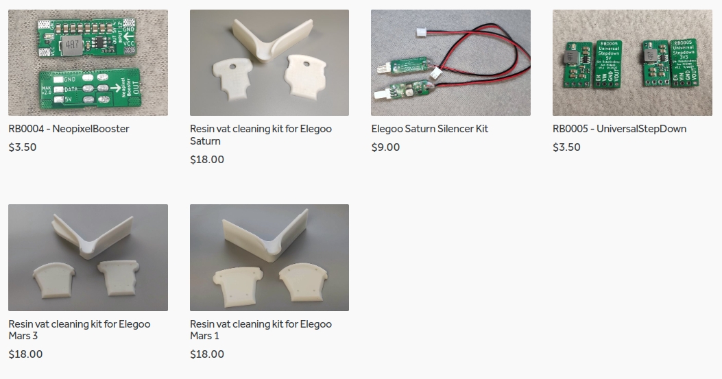
I launched new tank cleaning kits for Elegoo Saturn, Saturn S, Mars 1, and Mars 3. You can find them in my store.
Related Posts
- Multi-planar Slicing for 3D Printers – For Both FDM and Resin
- Open letter to the 3D printing community: Let’s be better in 2023! What should we do?
- Continuous Printing On LCD Resin Printer: No More Wasted Time On Peeling? Is it possible?
- About the Successful Quest For Perfect MSLA Printer UV Backlight
Thank you for your great work here!
You mentioned that parts keep shrinking for a few days before settling, and this is in line with my private, non-scientific observations. I suppose this kind of post cure shrinking would be uniform in all directions and therefore needs to be compensated along Z-axis as well? This would mean that we need to take measurements right after printing and washing but before post-print curing (A), and then again after full process and wait time (B). Then X and Y would need compensation for B, and Z for B-A.
I am also curious if shrinkage depends on parts size or thickness. Would a thin walled box shrink different from a solid cube? I suppose this could be tested by printing your test piece in different scales or same length but different cross sections.
Thank you again and keep it coming!
Your observation is right. If you need to compensate for the “rest” shrinkage you can use the same compensation I use for silicone molds. In that way, you will compensate XY by one constant (relatively large one) and Z by another one.
The dimensional stability depends on the shape. There are some interesting phenomena that I will describe in an upcoming post (it will be released somewhere next week).
I am slightly surprised that with such an extensive analysis that you have not mentioned slicer generated dimensional errors i.e. pixel rounding (other than the non square format of RGB types).
Whilst using dimensions in 0.1mm steps on a 50 micron pitch this might not be an issue on other types (47.25 or 37 micron etc) the chances of both ends of a part landing exactly on a pixel border is almost zero.
As a result when a part stops part way across a pixel the slicer has to determine if it should expose the whole pixel or not. How it does this by looking at how much is covered and also the 8 surrounding pixel isn’t published but can be different between slicers (and why I stopped using one slicer for technical parts).
However they tend to default more towards exposure than not. As a result of pixel counting (boy is that a pain) I found that quite often an outside diameter can be 1 or 2 pixels larger and internal dimensions 1 or 2 pixels smaller. As this is before any exposure, blooming or shrinkage takes place even if these errors were fully corrected the two parts would still not fit together!!!
The only reason I mention it is because the “exposed” image can be already over size the shrinkage rate may be higher than calculated in your method and the blooming less than calculated. The blooming correction is less of a problem as the correction used above will correct for the “pixel rounding” at the same time. However my typical shrinkage rates are slightly higher than yours.
My own test pieces does 100mm (in 10mm steps) and 50mm (in 5mm steps) and I can print this with errors in the 20-40 micron on all steps.
It is interesting that printing this on a 50 micron pitch and 37 micron pitch does give slightly different overall lengths using the same resins etc etc. which is how I ended up pixel counting in sliced files to try and check actual “exposed” sizes. A 1/8th inch hole or pillar was interesting as it’s 3.175mm size never matches pixel pitches
Hi Paul!
My main goal was to provide a tool for the community to measure the shrinkage and make the community aware of this phenomenon. This is why I intentionally skipped some of the details.
One of them is the aspect of pixel alignment and especially (which I plan to write a follow-up blog post) anti-aliasing. There is some pretty good work on how voxels grow by Autodesk and how to leverage anti-aliasing. At the moment, I think Chitu slicer handles anti-aliasing wrong. I have some work in progress on how to fix this and how to properly grow partial voxels.
Since my sample is heavily oversamples – it contains 6 measurement points in the basic version and 24 in the most exhaustive measurement, getting one or two values slightly doesn’t change the result much. It will only decrease the confidence of the measurement. Due to the statistical model, the method is pretty robust to errors, e.g, when you end up on the pixel boundary. Just give it a try and play with it. You should find out that indeed, the shrinkage is computed the same (possibly with less confidence) no matter the pixel alignment (except in some pathological cases where all dimensions are off by 1 pixel. But at the moment I am not sure if that is even possible with the distances I use).
Hi, the calculator gives a erosion factor, for me it is -0.06 . but chitubox has tolerance compensation a and b for both normal and bottom layer . should the -0.06 value be entered into both a and b for both normal and bottom layer
thanks!
Yes, both values should be the same.
I also wonder what the long term viability of resin prints is.
Especially after watching a YouTube video [Fake Tanks: Models at The Tank Museum] by the Bovington Tank Museum.
At 18:40 the curator explains why they don’t accept they don’t accept plastic kits as donations.
He describes how they’ve found models with a slight goo, which is a result of long chain polymers in plastic degrading over time.
Something similar, and a well known issue in the model railway world, happens with some buildings made by Triang (a UK toy company) until the mid 1950’s.
These where made from cellulose acetate, which resulted in these models becoming notoriously bendy.
Rather than polystyrene as used by the likes of Airfix, a material which can also become brittle in sunlight.
Sunlight, or more precisely UV, is important to us because it cures our prints.
Yet many of us have seen our prints, even small ones, crack because uncured resin has got trapped inside.
Or get tacky on the outside due to resin not being washed off.
A similar problem can also happen if 2 part resins not mixed correctly.
Which makes me think that if we are producing things for long term purposes, prime example being work for a art gallery, we might need to rethink our production methodology.
One solution could be to simply reprint the piece if degradation occurs.
Though for galleries any form of duplication raises questions about authenticity, status or value.
Or maybe use the 3d print as a former and use other materials for the final production piece.
For example, we might print a piece, create a mould and cast that piece in white metal.
Sources:
https://www.youtube.com/watch?v=yt-tqsdXZPw
https://www.rmweb.co.uk/topic/66228-tri-ang-models-in-cellulose-acetate-how-long-till-they-warped/
Jan –
How do you put these calculation outputs from you test print (model X-Y scale and tolerance compensation) in to Lychee?
I’ve been attempting this, but not sure I’m doing it right as I can’t seem to iteratively dial in both the tolerance compensation and the shrinkage/scale factor. For example I can get the outside diameters pretty darned close, but then the inside are off and then I do another measurement and correction and the inside is good, but the outside is off (by 0.1mm off).
Any suggestions?
Thanks – John
Resin seems to shrink differently depending on thickness. You test defines shrinkage for a 5x5mm rod. Im playing with a resin that shrinks almost nothing in XY at 25mm XY thickness and 1.03% at 5mm. But Z-seems to shrink at 1.03% regardless Z-thickness. So parts with different thickness in combination gets slightly deformed. Any good strategy for any such situation?
Hi, yes, this whole experiment assumes isotropic and homogenous properties for the resin. I assumed it was a sane setting (at least for pieces before post-curing) as I haven’t experienced any differences between shapes. It is different for thick parts that you post cure as the light cannot penetrate deep enough. Thus the middle no-so-cured part tends to prevent the part from shrinking.
I am wondering – what resin do you use where you observe different shrinkage?
Hi, I first noticed it with Jamghe Engineering Like – White. Later I printed out your sample with Anycubic UV Tough white, but as it flexed too much for any accurate messment, so i made it much wider (30mm) and at first it seemed to shrink much less than the first thin one, but now a week later, they seem to have shrunk about the same, from 106mm down to Thin=104.5mm/Wider=104.8mm (total length) so you might me right. But i read an article stating that resin shrinks differently depending on thickness, but i can’t find it now. I need to play more with this to be sure, when I have time.
Our biggest concern now is that parts seem to never stop shrinking 🙂 . The seller of a Magforms Rigid110 resin said it would only shrink 0.1% but that was total BS as same sample as above (106mm) is now 105.39mm a few days later = 0.57% and still shrinking. Anycubic UV Tough white has shrunk 1.5% and is even worse at 1.8%. I have tried to UV cure in a 60C water bath as one suggested, but it just warped the part more, but is still shrinking as the normal cured ones. I saw your very low shrinkage numbers on Siraya Fast Mecha, So i ordered it from abroad (Siraya is not available here) We plan to make machine parts and is looking desperate for a suitable resin, but to no avail. Any suggestions of a form stable, short shrinkage duration, non-brittle resin?
** Anycubic UV Tough white has shrunk 1.5% and Jamghe Engineering Like is even worse at 1.8%.
I am still running some experiments regarding shrinkage. It seems that Siraya Tech Fast continues to shrink for about 3 months after the final cure (at room temperature). But it seems to fade exponentially.
At the moment, I don’t have a tip for “perfect engineering resins”. All of them are always a compromise. Fast Mecha suffers from overgrowing, but on the other hand, its mixture with Tenacious seems relatively durable and strong (no precise measurements here). If you are looking at something very tough, I can recommend OverhangsLab Model resin or LITLIQ TH50 resin.
The other option is to explore industrial resins for laser and DLP printers. They are very expensive and require 20-60s exposure on LCD printer, but they can offer interesting mechanical properties. But I don’t have a tip in this area.
Im getting this:
The computation failed. This is probably a bug and you should report it on the project’s Github. However, at the moment, try tweaking some of the number a little – it might help.
I have triple checked my numbers but still get this error
Please, open the issue on GitHub and share the precise numbers so I can reproduce the issue. There is a problem that my implementation of the numerical solver for the least square sometimes doesn’t seem to converge.
By “tweaking the number” is meant to change them by 0.01 mm. It can help to get the solver out of the non-converging zone.
Solved. It seems to be a rounding error. 99.40 and 99.42 will work, but not 99.41.
Really great post and very interesting! I’ve been compensating for a couple of years now since I have been printing. Accuracy is really critical to me – I print dental models and materials. I would love to hear your opinion if you think there is a critical minimum dimension when you can start to compensate?
The reason I ask is that up until now I have been pretty larger objects – dental models (probably 15mm across) in the arch. I usually compensate 2 pixels on outer surfaces which I find means that when I seat corresponding parts together they fit really well. Normally for the crowns I have been milling them (these can be anything from 0.1-2mm thick) which is super accurate. I have been printing some temporary crown resin which is great but compensation on the thin sections (i.e. 100-500 microns) means that even compensation of 1 pixel would means the fine parts disappear or massively reduce in size. I have therefore limited compensation to printed parts > 1mm and do not use it for super fine detailed parts. For a more real world application I presume this would also apply to those printing miniatures etc?
Regarding the scaling factors, again, is this relevant for prints of all sizes? If I am printing only things of really small dimensions (1-15mm) I presume it would be better to use a much smaller calibration model and not use a larger calibration model/values for these prints? Keep up the great work!
Is it correct to scale the model AND apply the tolerance compensation?
Yes, the first corrects for shrinkage, the second for light bleed.
Do you have any idea why my scale number would be lower than 100%? I have taken the measurements over the course of a day and am still getting around 99.8% scale. Do you have to wait a few days to get accurate numbers? Thank you for this write up and method though, much better than some of the other shrinkage calibration models.
Hi Jan,
I have tried your test part to calibrate my brand-new Photon M7 max, and I work on that subject for 2-3 weeks now. What follows is also a reply to Paul M’s post (June 25,2022) about pixel rounding, M7 max have big pixels (46×46µm) this may be why I notice the issue.
The real limit using your test part is effectively that all dimensions are rounded to 1 pixel by the slicer (Lychee for me). When one comes close to ‘the solution’ after printing with different corrections it does not converge any more and the measure over the 6 different points are not “coherent”. Note that the roundings change each time you change with every new correction coefficient, that is where the issue is.
My solution is to use different test pieces consisting in two rings, one with external diameter equal to the internal diameter of the other and then apply the mathematics that you propose. (I use rings as I feel it is easier to measure with a caliper). For each new correction coefficient, I (slightly) modify the real asked thickness and diameter of the rings so that they are an (even) integer number of pixels.
Now the process converges, and I obtain very good results. As a partial evidence : the two rings enter one in the other without lag (and not using sandpaper or hammer 😊) and more surprisingly, I am able to disassemble them!
Regards,