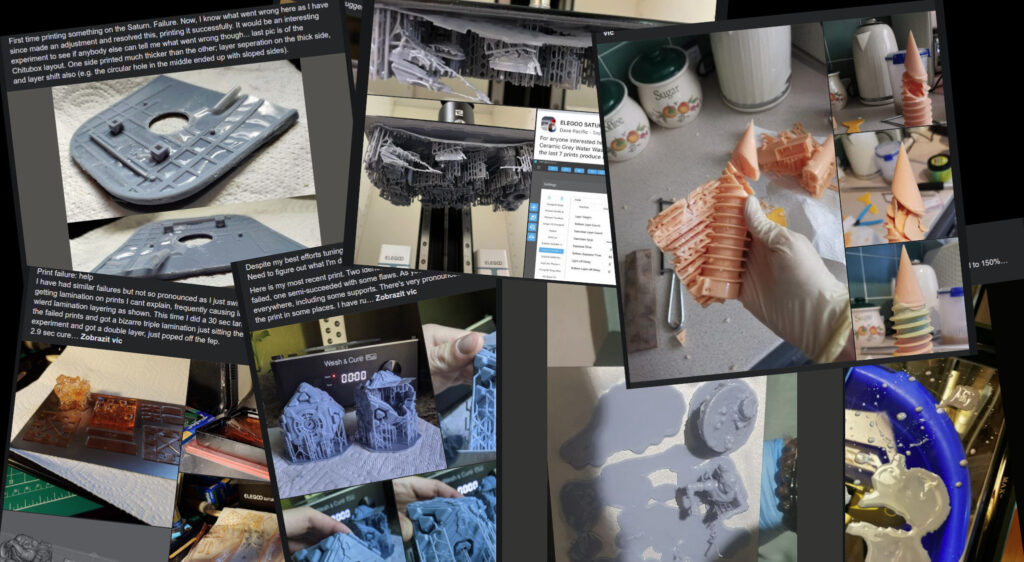
When you scroll through the various Facebook group about resin printing, you see quite often questions about the following topics:
- “my prints are not sticking to the build plate”
- “my layers separate”
- “my prints have a rough surface”
- “I have a large elephant foot/squished bottom layers”
In the first two cases, people often advise “increase your bottom layers!” and “increase your bottom exposure”, “lube FEP”, “sand your build plate!”.
But I think such advice is wrong and the best advice for all four cases should be “Introduce a light-off time”. Why? Let me walk you through a series of experiments and observations. It will be a long read, but bear with me – it is an actually simple puzzle just with multiple factors. And as we will see at the end, the same advice also applies to solving the rough surface case and also (partially) the elephant foot. We will also learn, that printing at layers thinner than 50 µm does not make much sense and it can actually degrade the print quality and precision.
Note that I have previously touched on this topic in my blog post Improving surface finish of hollowed SLA 3D prints: one aspect of blooming.
Experiment 1: What is the maximal layer height?
Let’s get two pieces of glass. We will tape 1 mm (1000 µm) thick spacers on the side of one of them. Now we will make a small droplet of our resin of choice, cover it with the second glass. We put this sandwich on the screen of our printer and crank up the tank clean function to 60 seconds (basically we want to expose our sandwich from one side). Once cured, we disassemble the sandwich and wipe out the uncured resin. We are left with a thin disk which thickness we can measure with a micrometer.

The exposure setup

Resulting discs of resin

Mesuring the thickness
For illustration, there are thicknesses of the resins I commonly use. Please, consider these numbers as rather illustrations – I only made two samples. If we would like to obtain proper numbers, we would have to repeat the experiment multiple times.
- Siraya Tech Fast White: 540 µm
- Siraya Tech Navy Gray: 320 µm
- Siraya Tech Sculpt: 200 µm
So – what did we measure? The maximal layer thickness we are able to achieve. The resins formula is designed such that it absorbs UV light within several hundreds of micrometers. Why? To avoid cross-layer curing when printing overhangs and bridges. You can see that the number varies on the resin, but is pretty low. Even if we crank up the exposure much higher, we wouldn’t cure a thicker layer (there is a linear and non-linear region regarding the thickness for a given exposure, but this is too much detail for our purposes at the moment).
That means that we cannot print layers thicker than this value, as the resin does not cure and thus, does not stick to the previous layer. Actually, it will be a little less as we need to stick the new layer to the previous one.
If you are wondering why we covered the top of the resin with glass: the resin does not cure when exposed to oxygen. So we want to eliminate this factor from our measurements. BTW: The curing inhibition caused by oxygen is the reason why everything contaminated by resin becomes sticky – the resin is left in a thin layer, exposed to oxygen, and never cures. Measuring, how thick is the inhibited layer is a topic on its own for another blog post. Also, the cover glass allows us to retain proper drop thickness via capillary forces.
Now we can repeat the experiment, but instead of curing the resin properly (with long exposure), we use standard exposure time. We obtain new values:
- Siraya Tech Fast White: 160 µm
- Siraya Tech Navy Gray: 90 µm
- Siraya Tech Sculpt: 75 µm
With about 50% of the normal exposure, we get similar numbers, but the resin disc is quite fragile:
- Siraya Tech Fast White: 130 µm
- Siraya Tech Navy Gray: 80 µm
- Siraya Tech Sculpt: 70 µm
These numbers tell us the maximum layer thickness for regular exposure we use during printing. If we make a thicker layer, the layers won’t properly stick together and we see a layer separation or prints not sticking to the build plate. Note that this number is also dependent on the temperature – the warmer the resin is, the quicker it cures. So in cold environments, the thickness will be probably lower for lower ambient/resin temperatures.
Note that the resins that are marketed as “high detail” usually block the UV light more to prevent cross-layer curing (as we can see in the example of Sculp here). That also means they are much more likely to experience not sticking or layer separation. We can also conclude that printing on much lower layer thicknesses, e.g., less than 25 µm, does not make much sense as the resin will easily cure-through and cover all the details. Therefore, we lose precision and we only increased the printing time.
This gives us a lead – when the print is not sticking to the build plate, is it possible the resin is not curing all the way through? Also, we can notice that meanwhile, the bottom face of the resin discs is nice and hard, the top is quite soft. So the actual maximal layer thickness can be slightly lower than the values above. They are just the upper estimate on the maximal layer thickness.
Experiment 2: How thick layers can my machine produce?
For the next two experiments, we have to get a little technical. We need a way of measuring the build plate position in the Z-direction. Therefore, I took my Elegoo Saturn and modified it a little bit:
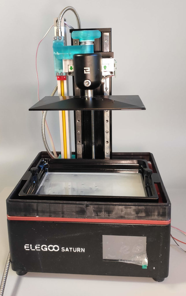
The modification of the Saturn

The modification of the Saturn

The modification of the Saturn
What you see is a replaced build plate arm (machined out of aluminum) and a linear scale with a resolution of 1µm attached to the printer (it is attached via printed components as it does not transmit any significant load). The setup is not suitable for regular printing, as removing the build plate is complicated, but it serves well for our experiment. The linear scale is connected to the microcontroller, so we can read the actual position of the build plate. I also connected the stepper driver signals (step and direction) from the printer’s motherboard to the microcontroller so I can read out the “intended build plate position”. With this setup, let’s get printing will be printing the following model (basically 50×50×3 mm cube that shrinks to half in the middle).

With this setup, we can measure how much the build plate lags behind the intended position (maybe better said the position of the motor). I measured that the build plate lags behind the motor quite a lot – up to a few millimeters during peeling. That is expected and you can see by your own eyes how the Z-axis column bends. However, it also lags when sinking the build plate into the resin. The actual position of the build plate lags behind the expected and it slowly “catches up”. When the printer stops moving, the base layer is about 260 µm for Fast and 340 µm for Sculpt. However, if we stop the printer and let it sit, it slowly converges to the desired layer thickness. After 30 seconds of rest, we get 80 µm layer for Fast and about 100 µm for Sculp. The layer never reached the desired thickness of 50 µm for the base layers. This layer thickness is actually higher than what we can cure with regular times! What would happen if it was even higher? The layer would not stick to the build plate as it wouldn’t be cured through.
For completeness, I will just add that once we print over 2 mm of the model, the real build plate position tracks the desired one more precisely and it can settle to the desired position within 10 µm. The lagging also practically disappears.
Experiment 3: Why are my layers thicker than intended?
In the previous experiment, we showed that on Elegoo Saturn, the layer thickness is much higher in the base than we anticipated. Luckily, the setup I showed above has one trick in the sleeve – there are tensometers in the build plate arm, so we can actually measure the forces that push or pull the build plate arm.
We can expect the following forces to be present:
- some friction of the axis itself, that should be negligible,
- peeling forces of the cured resin when lifting,
- some forces when we sink the build plate into resin.
Let’s see what printing looks like:
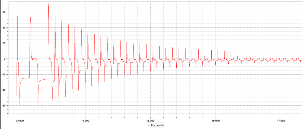
We see that the forces are quite large – both sinking and lifting can yield forces up to 120 N with Siraya Tech Fast (that is 12 kg equivalent), even more with thicker resins (I measured up to 200 N – that is roughly 20 kg equivalent). We can see that the forces get lower and lower with increasing print height. What happening? My interpretation is that when we sink, the build plate has to push away the viscous liquid (resin) and form a really thin layer. This creates a lot of resistance that pushes the build plate up. Similarly, in order to lift the build plate, we have to fill in the void space below the build plate with resin. The resin has to flow in via the narrow opening (the current print build), so it is larger in the bottom layers and negligible in the higher layers as there is a much large space where the resin can flow in.
My test print has a narrowing after 1.5 mm, so I can actually measure the peeling forces caused by the cured resin sticking to FEP – by measuring the difference between the lifting force of the 2500mm2 crosssection and the 625mm2 one. In my setup they are in the order of units of newtons, so they are pretty much negligible for this area. You can see the change in the timepoint 16220. Also, note that there is practically no difference in the peel force between bottom exposure and the normal exposure. This basically shows that the common saying “If you cure too much, the print sticks to the FEP and not to the build plate” is wrong.
The thicker resin, the bigger resistance. I have actually measured that really thin resins like Siraya Tech Simple can have about half the resistance compared to the thick ones, e.g., Siraya Tech Blu or Sculpt.
Compared to our expectation, we can see that:
- the peeling forces of the cured resin are pretty much negligable, but
- the sinking and lifting forces are huge when the build plate is close to the bottom of the resin tank.
The obvious question is: what does this do with the printer? I modeled the printer and simulated it in Autodesk Fusion. The conclusion? The construction is really flexible and it can be easily deflected by the forces we measured. See the results of a simulation simulating the printer trying to peel the bottom layer (note that the visualization of the simulation is exaggerated to better see what is happening).

See that the weak point is actually the base plate, not the Z-column.

Simulation of peeling. Note that the visualisation is exaggerate.
You can actually see the bending with your eyes. Using an indicator, I have measured that in the worst-case conditions the motor has to move the build plate up by 5 mm before it actually starts moving – this is how huge the forces are and how flexible the construction is. This is also the reason why Saturn needs much bigger lifting distances compared to e.g., Mars. How flexible it is you can also see with your own eyes – just take a side look at the Z-axis column from the side when will next print.
The interesting observation is that the Z-axis column is not the weak spot, but the base plate is. Therefore, I think the reinforcements added to the post-preorder batches of Saturn don’t have practically no effect.
Since the construction deflects and acts as a spring, we have an explanation for the thicker layers than anticipated – the resin causes resistance that bends the construction. It gets preloaded and still pushes the resin away in order to reach the desired build plate position.
Note that Elegoo Saturn uses a rubber motor mount to prevent the motor vibration to spread and also to compensate for axial misalignment of the motor and the nut in the build-plate arm. This partially adds to the overall flexibility. I have replaced the rubber motor mount with a rigid one and I will share the results for this replacement with you soon.
Closer look at the sink-expose-peel cycyle
My microcontroller also captures when the UV light is on. When plotting this, we find out something shocking – the build plate is still moving down when the resin is curing! And it stops moving before reaching the final destination. That means that the build plate has reached the maximal cured resin layer thickness and therefore it does not stop:


Build plate moving down means squeezing out the resin. Build plate moving down during UV light on? That means partially cured resin squeezing out. That also means blooming – the rough surface and dimensional inaccuracy. Also, in the worst case, it means the build plate never reaches below the maximal layer thickness and you get a print that did not stick or features layer separation.
Also, since the resistance when sinking is the highest in the base layers, I tend to believe it might be one of (or maybe the major) factor contributing to the elephant foot/squished initial layers on the prints.
What conclusions can we make from the experiments?
We should have pretty much all the observations for mitigating most of the problems during resin printing. Let’s revisit them and explain how they are all caused by resin viscosity:
How can I solve my prints not sticking to the build plate?
When your prints do not stick to the build plate it means the layer was not properly cured through so it can actually stick. There can be several sources of this:
- Wrongly levelled build plate – if it is tilted, the layer is thicker on one side than on the other. Once it reaches the critical thickness, the resin does not cure-through. However, having build plate properly levelled isn’t a complicated and I guess most people do it right.
- The build plate is not completely flat. There are people sanding their build plate because they think the build plate is not flat. I measured the two build plates of my Saturn and both of them are flat within 30 µm. That is enough for the first layer to stick (as we have measured that most resins cure properly withing 200 µm, so 50 µm (layer thickness) ± 30 µm (the build plate deviation)). Sanding it without proper equipment and measurement probably will make it more curved than it is. One aspect is that sanding creates rough surface and the resin sticks better to rough surface in my observation. Nevertheless, for most of the printers, this is not an issue.
- The printer construction is flexible and the forces are huge. Therefore, the build plate does not settle in the position and the printer is printing thicker layer. I think this is the main reason why people’s print don’t stick to the build plate.
The solution is simple – introduce the light-off delay so the printer has enough time to squeeze out the resin and to properly settle in position. Personally, I use 40 seconds of rest time for the first 0.5 mm. This gives enough time for the printer to settle in position. Why 0.5mm? This is a large enough gap to make the suction resistive forces from the build plate negligible. With this setup, I can use 2 base layers with a 10-second exposure on my machine since the layers are indeed 50 µm thick and they don’t need much exposure to properly cure completely. Unfortunately, with the current dumb Chitu firmware and slicer, you cannot automate this process based on a layer crosssection and distance, and I manually change the light-off delay during the print. With this setup, my prints stick perfectly. It also has one advantage: there is no elephant foot!
Also, our measurements explain why Siraya Tech Fast is so popular “and the best resin with zero failures” and Sculp “nice, but extremely hard to print”. Fast cures-thought a lot, therefore it sticks even when the build plate is not positioned properly, but Sculp cures through only in thin layers.
How I can remove the elephant foot?
Back in the day, I wrote a tool for reducing the elephant foot on the prints. Now, this functionality is built-in Chitubox and other slicers. However, I stopped using the compensation completely. The compensation does not work properly as it just shrinks the footprint, but it does not reflect actually how the resin grows. Also, when you print tiny objects, small features get completely lost. Compare the shape of the tooth on a gear:

The proper shape

The compensated shape
In my previous blog posts, I claimed that the elephant foot is caused by exposure bleeding during the high light-off times and also by the light reflecting against the shiny build plate. I was wrong.
Based on the experiments above I think there are different mechanics in place. Elephant foot is caused by the partially cured resin being squeezed out. Why it cannot be the light bleeding outside the perimeters of the model profiles? If it was the light bleeding, then the elephant foot could be at most 300 µm large as we cannot cure a thicker portion of the resin. But it is often much more (at least 500 µm in the base layers).
Let me point out, that the above is a simplification; there is definitely some light bleeding out as the LCD does not block the light completely between neighboring pixels and some light can reflect from the build plate. But the effect of these phenomenons is much smaller compared to the amount of resin being squeezed out.
And, indeed. Having the first 0.5 mm printed with 40 seconds of rest time and 10 seconds base exposure on my Saturn practically eliminates the elephant foot on my models. See the comparison (the gear with elephant foot has actually turner on the 0.2 mm compensation(!), the gear without the foot is just printed with no compensation, but with light-off). The results are astonishing:

Gears side-by-side on the build plate

The gear printed "standardly"

Comparison

The gear with light-off

The gear printed "standardly"
How can I prevent blooming?
There is another phenomenon I briefly touched on in a previous blog post: blooming. Blooming appears as a rough texture on the models often with a visible line that correlates to with large cross-section. Those are observations from my blog post and the Photonsters experiments. The Photonster assumes that when the resin is cured in large cross-section areas, the curing reaction catalyzes itself (just the presence of cured resin makes it faster or the heat makes it faster) and it just “blooms” outside perimeters of the models. They propose to solve this problem by applying patterns to the large cross-section areas like this:

Curing pattern in UVTools: Photonsters https://www.facebook.com/Photonsters/photos/p.1353727301747913/1353727301747913/?type=3&av=719355768518406&eav=AfYv0BOrfFACpvtsr7xfknLsiK4BApPSh9BiCvxL59N5ZZqUqCrudWrmJeBBKXo7e68

The result: Photonsters https://www.facebook.com/Photonsters/photos/p.1354856848301625/1354856848301625/?type=3&av=719355768518406&eav=AfaklR0QtyykjgcHkZfhy4yIEMJTE5cKV_SG_2sPrVXOt6frA5yxrFJ5fUhSFBpcvoU
It seems that it helps, however, after these experiments above, I think the pattern might only slow down the curing and therefore, provide time to settle or provide “escape channels for the resin when squeezing it out. I can replicate the same positive results just by letting the printer sit in place and settle in position. Therefore, it is likely to me that the effects of self-catalyzation are at least not that significant and the biggest problem is actually again, the resin pushing against the build plate. So again, the solution is to have a proper light-off delay before there is a large cross-section being cured.
Also, note that according to my observations, you should include all areas surrounded by perimeters in the estimation of a cross-section. It seems that the air trapped in the forming cavity is pushing also against the resin – see the experiments.
How can I prevent layer separation?
A similar effect to the thicker bottom layers can happen anywhere in-middle of the print. There just have to be a bigger cross-section or you use a thicker resin and your build plate does not settle in position and therefore, you get a ticker layer. In that case, your layers separate as the new layers are not properly cured.
The solution is again to use a light-off delay. At least as the first help.
People’s printing profiles: Another evidence suggesting problems with resin squeezing
If my experiments above don’t persuade you that most of the problems are actually caused by the resistive forces when the printer is squeezing the viscous resin into a tight film, there’s another hint I might be right.
If there are no forces that the ratio between normal exposure and bottom exposures should be about the same across different printers. However, if you carefully examine most of the Google documents with exposure settings on the internet, you find that for larger printers people use higher base layers exposures (relative to the standard exposure). This is due to the fact that the larger build plate yields bigger resistance and therefore, people have thicker base layers on larger printers and, therefore, they have to use longer exposure times.
Also, most people dislike printing directly on the build plate as they often have failures. This is caused by the fact that the model on support is separated from the build plate by a region of thin supports. Therefore, the problematic region near the build plate is “handled” by the supports that are often over-cured just to make them stick.
Conclusion
I hoped the blog post helped you to understand the basics mechanics of printing a single layer on a resin printer and with this knowledge, you will be able to better diagnose problems with resin printing and you stop doing random stuff “just to make your models stick”. Note that I am not saying that people can’t have their build plates improperly leveled, they cannot print in a too cold environment. They can, but I think most of the problems above can be solved in an easier way. Introducing the delay doesn’t cost anything, it is simple to perform and OK, the test print will take longer to complete. But that is a little price to check for one, but highly probable, cause of the print failures, don’t you think?
There is also one case where the light-off time does not help. And this is insufficient peeling lift when the layer does not peel completely. It peels finally after a couple of layers are printed, but then, you have “a hole” in your model and thus, the first layer after that will be actually pretty thick and you will experience layer separation or half of the model sticking to the resin vat.
I also that after reading this you will no longer be scared of printing your models directly on a build plate and you won’t automatically put everything on supports as it usually sacrifices print quality in the form or support attachment point marks.
Also, as bigger and bigger resin printers are coming (Elegoo Jupiter, Phrozen Sonic Mega) I think the problems with layer thickness will be more severe. There is no wonder that Prozen put holes in the build plate to mitigate the resistance during sinking the build plate.
Most of the problems highlighted above could be solved with more rigid machines (e.g., by using 3 Z-axis columns), but I guess we would ultimately reach the stress limit of LCD. The forces that resist the build plate from sinking also apply to the LCD. This is why there is thick glass below the LCD on most printers. This glass provides the support structure so the LCD can withstand the pressure of the resin being squeezed into a thin layer. I also have several ideas that would remove the forces completely, but they need some extra work and are not ready to be published.
However, most of the problems could be solved purely in a software manner. We could automatically compute light-off delays, we could probably solve elephant foot by multiple exposure patterns for a single layer. We could also measure the forces and actual build plate position and make special sinking/peeling cycles with feedback. Unfortunately, most of the resin printers are currently locked in the primitive Chitu ecosystems… But this is a topic for another blog post. If you don’t want to miss any news, be sure to follow me on my social media. Links are below.
Recent news: My open letter to the 3D-printing community
I love the 3D-printing community, but I think there is room for improvement. Let's get better in 2023! Read the full letter.
Support my work!
If you like my work (these blog posts, my software and CAD models) and you would like to see more posts on various topics coming, consider supporting me in various ways:
- You can become my sponsor on Github.
- If you prefer, you can also become my Patreon.
- You can buy me a coffee on Ko-fi,
- or you can buy something from my Tindie store (also see below),
- Or you can just share my work!
If you are interested in knowing what I am up to and recent sneak-peaks, consider following me on social media (Twitter, Instagram, Facebook).
My store offers
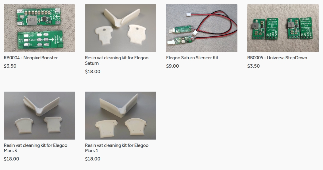
I launched new tank cleaning kits for Elegoo Saturn, Saturn S, Mars 1, and Mars 3. You can find them in my store.
Related Posts
- Multi-planar Slicing for 3D Printers – For Both FDM and Resin
- Open letter to the 3D printing community: Let’s be better in 2023! What should we do?
- Continuous Printing On LCD Resin Printer: No More Wasted Time On Peeling? Is it possible?
- About the Successful Quest For Perfect MSLA Printer UV Backlight
Thanks for the post. It is really interesting and some great info overall. My question is how do you implement your light off settings on your prints? You state: …”I manually change the light-off delay during the print. With this setup, my prints stick perfectly. It also has one advantage: there is no elephant foot!”, that sounds great and i want to try it as well, but I have no idea where to start on my Elegoo Saturn.
I set the light-off delay on regular layers to 40 seconds and start printing. Once 1-2 mm are printed, I use the “gear” button on the printer to disable the light-off, and therefore, speed up printing.
Yes, I am curious about this also!
I just found out that if you use firmware 4.4.3 and Chitubox 1.9, the feature I was using is missing. I didn’t notice that as I was using an older firmware and Chitubox 1.8. Unfortunately, the new firmware does not allow you to edit the value manually during print, and on top of that, it ignores the rest time for the first layer. Also, Chitubox 1.9 does not allow you to set separate rest times for base and normal layers.
Very interesting work and great job! Would a viable workaround in Chitubox 1.9 be:
-Bottom layer count to 10 (=0,5mm @ 50 micron layer height)
-Bottom exposure time to something more reasonable, eg 4x standard exposure (~8-10s)
-Bottom Light-off delay to movement time + 40s (so eg 46s total)
For a smaller build plate, eg of a Mars 2 Pro, would a delay 30s be sufficient? Have you perhaps conducted such tests on these smaller machines as well?
Thank you very much for your awesome work and insights!
Ok, nothing is working in terms of delaying the first cure on firmware 4.4.3. Neither adjusting “wait before cure” nor “Bottom wait before cure” via UVTools work on the first layer, while it does work nicely for all other layers. Which firmware version did work for you?
I was working on an older firmware (don’t remember the name). Recently I upgraded to 4.4.3 and I noticed that it is completely broken. I am working with Tiago on fixing this and there will be an upcoming post with a fully automatic procedure for this that works around this stupid bug in 4.4.3
Great, I hope you will post a fix soon! 🙂 While testing I also noticed that the light off/ rest times are completely ignored when pausing a print, or more specifically in the cycle after resuming the print.
This is the most thorough investigation on several of the major issues people (including myself) face when 3d printing. I’ve been having issues with the bottom layers being far too thick causing issues with a particular part I am working with.
Within Chitubox 1.9.1, I set the Rest Time After Retract to 5 seconds just to see what effect it may have without having to wait so long for the print to finish. Even with 5 seconds, the print showed a significant improvement in reduced elephant’s foot, blooming (I learned that term here), and as a bonus, the part warped less post-curing.
I’m now going to try another print with a longer ‘Rest Time After Retract’ to see if the anomalies improve further. The print will take a very long time without the fix to allow the value to only apply to the first .5mm, but should be worth the experiment.
Thank you very much for your work on this. Looking forward to the official automatic procedure you come up with. It is much appreciated!
After running another test with 30 seconds set in Chitubox for “Rest Time After Retract”, the print came out near-perfect. As you stated, I set the bottom layers to 2 @ 10s exposure and a 2.5 s exposure time for the rest of the layers (I’m using Elegoo ABS-like Grey). I also set the Transition Layer Count to 0 since I figured that now the bottom layers aren’t getting completely fried by the 20s I used to have and there are only 2 of them, there isn’t much need to transition. There is zero blooming and all layers are very smooth.
I also turned off the ‘Bottom Tolerance Compensation’ and although a tiny elephant’s foot can still be felt, it now looks more like it could actually be the light bleed from the over-exposure. I’ll probably set both the inner and outer back to a small value and see how that works.
For reference, I’m printing a 76.2mm x 76.2mm x 8.5mm rectangular box printed directly on the build plate.
Again, I’m very grateful for your work on this set of problems. Extraordinary execution and solution!
Which Slicer are you using?
thank you Ryan for your comment! i appreciate you posting because i used your settings and it was a game changer for me. and obviously thanks for the whole article Jan, your hard work is very much appreciated!
Thank you very much for this valuable information. I feel like I’ve taken a giant leap forward in 3D printing, which is still very frustrating at times. I will make a print with these settings with Lychees. I’ll come back to you with the results. Best regards, and thanks a million again for sharing. Fred
This is the best analysis I’ve seen yet. Real experiments, sound engineering. I’m new to resin printing, and this has saved me huge amounts of time.
No need for 40-60sec exposures, compensation, etc. It’s really very simple- just letting the mechanism settle!
The vast variety of posts and video blaming esoteric optical and metallurgical factors etc. for blooming and plate adhesion failure are just rubbish.
Lychee slicer is on the right track, with separate Light Off Delay for base and normal layers.
Better yet, UVTools allows you to specifically set WaitBeforeCure for base and normal layers.
As for the Layer 0 failure to wait, that appears to be a firmware bug. UVTools has a workaround script,
which adds a dummy layer 0, with no following movement. See https://github.com/sn4k3/UVtools/discussions/402,
and file ScriptDebandingSample in https://github.com/sn4k3/UVtools/tree/master/UVtools.ScriptSample.
Keep up the great work!
I’ve been beating this drum for about a year now on Mono X FB groups and managed to convince a few of the owners. Nice presentation that pretty well mirrors my findings:
Screen deflects significantly, as shown by initial slice that’s significantly thicker at the centre.
Column leans back due to slight twist in the deck, slight bend in the column, twist in the attachment of the gantry to the carriages, and the take-up of clearances in the linear carriages.
Many thanks for all those experiments and great conclusions. I was having trouble getting accurate Z dimensions making some precision moulds on a Photon Mono X. Inter-layer distance was reduced especially just following a large-area layer which must have been holding up the descent of the build plate.
Now I can get superb results (very accurate and no blooming), by adjusting the light-off time. I added a dial test indicator to observe build plate height in real time, i.e. a bit like your DRO scale but simpler. Starting with 100s light-off time, I can manually adjust down the time as the print procedes, checking that the plate always settles to within 20um of target height before exposure.
I might experiment adding load cells to the motor mount, and see if I can think of some way to automate the process via force feedback as you mentioned.
Hi Jan thanks for your findings.
Quick question. If i’m not mistaken lychee let you change profile at certain layer count.
So what about setting light off delay (high) for the first 0.5mm then switching profile and continuing with a shorter light off delay?
Can I just skip uv tool this way?
Thanks
If that Lychee allows you, of course you can use it and skip UVTools. The advantage of UVTools is that it can add rest times based on the layer cross section.
So if I’m reading it correctly i need 40 ish seconds light off delay for the first 10 layers (at 50µm), on other layers rest time before and after curing to be able to limit suction forces, perfectly cure any layer and avoid delamination, based on cross section (via UVTools)…Am I missing something?
Hi Jan,
You give me the good explanation for printing resin and it’s so cool to read that !
Just one question, you say :
“The advantage of UVTools is that it can add rest times based on the layer cross section”
and it’s exactly what I am looking for but I could not find any tool or script anywhere in UVTools to make that.
Could you give me the way please ?
Thank you for all you give !
François
Great articles Honzo, your research is amazing. The best read about printing I have ever seen in a long time. (I’m in FDM printing for many years and in resin for a while also).
I have followed your advice and I think I managed to take it even step further.
Two days ago I started to test my new Mars 3 Pro and for my test prints I choose big textured tiles (85×97 mm) that are exactly only 1mm thin like this one: https://imgur.com/H2gZGof
Printing directly on build plate with no supports is the best option here. After initial bed calibration made acording to official manual and with some well rated print profile from Lychee library for my resin (Elegoo 8k standard resin) I run first print and what came out was monstrosity with thickness of 2,6mm on front side and 2,2mm in the backside (near the Z column) with damaged details. I wanted to get finally to the buttom of this issue because I experienced similar problem on my Photon mono before and it made no sense to me. So I started googling and found your articles and finally understood what is really happening here, thank you for that really.
After recalibration of bed with your method (dummy print…) and setting light-off delay for first layers to 60s and lowering retraction speed to only 0,1mm/s I had massive improvement. Prints were now between 1,3-1.6 mm in thickness.
After that I tried new aproche – setting variable thickness for buttom layers because only logical explenation for still existing difference in thickness was that the real bottom layers can’t be intended 0,05mm but are much more. So I started experimenting with bigger bottom layers. At first I tried layer thickness of 0,1mm, than 0,15mm and even 0,2 and with every step the resulting thickness of the print went down. In the end I ended up with first layer set to 0,3mm, second layer to 0,2, third 0,1 and 0,05mm for the rest. For layers after first 1,5mm of height I think it is safe to increase speeds of retractins and decrease light-off delay. At this point I can print the test file in its real dimensions. Final thickness of my test part is between 0,95-0,97mm on all sides.
I can send you all of my settings if you are interested.I’m currently running more test prints with other slight tweaks to exposures and retraction speeds for first 3 layers.
I think overall this is the best way to print first layers because with big layers like this the construction of machine can finally handle preasure of resin in first layers just fine and you can avoid all deformations.
So I was doing some more digging with dry printing and stop watches.
It appears Mars 3 Pro has some firmware hard override for first layer. I found out it doesn’t matter what speeds and “light-off delay” you set for first layer (even “wait before cure” added in UV tools doesn’t do anything). The printer acts the same every time, it homes, lifts about 2-3mm and goes down again quite fast. Exposure then starts imediatly. I have even try to turn off burn in layers completely because I use separate settings for first 0,5mm of print anyway but even this din’t help.
So in the end only thing I can change for first layer is layer height and exposure time. This is the reason why setting first layer to 0,3mm in my previous comment helped so much. But it is not optimal fix. With some resins this could be problematic. I would much rather have printer that works as intended in the first place.
From the second layer it seems working fine acording to slicer settings.
I’m slicing with Lychee Pro.
Any suggestions?
My last idea is to make some dummy layer in place of first layer but I’m quite angry with Elegoo that I’m even forced to think about workarounds like this. (insert Picard’s facepalm here)
Just found out your later post: https://blog.honzamrazek.cz/2022/02/a-step-by-step-guide-for-the-perfect-bed-adhesion-and-removing-elephant-foot-on-a-resin-3d-printer/
I should have read everything first, sorry… But at least I can see I was quite on a good track with my research 😀
This may be the single most important resin 3d printing article ever written and should be considered required reading. As printers get larger this problem gets even more pronounced and without an understanding of what is happening (the increasing ratio between viscosity to printer rigidity), it would is incredibly frustrating to try to debug.
Thanks for the post. My question is a bit off-topic, but nevertheless:
> The curing inhibition caused by oxygen is the reason why everything contaminated by resin becomes sticky – the resin is left in a thin layer, exposed to oxygen, and never cures.
So what does this mean for a very common recommendation to cure the contaminated paper towels/gloves, supports and failed prints under the sun before disposal? Is there a better way to cure resin leftovers before disposal?
Sir, you are an engineering genius! I have begun printing on my Elegoo Saturn 2 (using Lychee Slicer) with a “light-off” delay setting, and the improvement is phenomenal. Previously, I was losing a LOT of models to delamination failures, but now the failure rate is almost zero.
Nice!!!
Just wanted to add this for Anycubic people. I was having major trouble getting a good print on my Anycubic. Wait time like this is just not supported… but they do support “advance control mode” with speeds for ‘[0]’. That’s the lowest part. So instead of adding a wait time, I just put the speed at 0.05mm/s (that’s 3 mm/min) and lift height to 0.5mm (that’s 10 seconds). You can just see from the resin in the tank that it settles before the UV goes on. I tested it with some tests on Siraya gray tough resin (2.4s exp / 10s exp) and that seems to work.
For the bottom layers I’m not sure yet and I’m still running tests… apparently it’s not so simple to get the model to stick furthest away from the bed.
Thank you for this excellent article that I read with great attention. I am faced with a loss of dimensions in the first layers of printing. Not afterwards. If I print 5 cubes of 1cm side placed in the north, south, east west and center of the plate my cubes measure: N=9.2, S=9.12, C=9.14, E=9.2, W=9.3.
I can’t find any resource allowing me to understand where this loss of dimensions comes from.
You haven’t provided enough details – what is the intended size? Nevertheless, I would suspect one of two:
– resin shrinkage: https://blog.honzamrazek.cz/2022/06/getting-perfectly-crisp-and-dimensionally-accurate-3d-prints-on-a-resin-printer-fighting-resin-shrinkage-and-exposure-bleeding/
– uneven backlight of your printer: https://blog.honzamrazek.cz/2022/12/about-the-successful-quest-for-perfect-msla-printer-uv-backlight/
Hi Jan. I must begin by saying that the scientific methodolgy you use, to investigate the multitude of resin printer issues, need to be high commended. There are way too many “ideas” out there which are complete and utter nonsense.
My problem, as experienced by many 3D resin printer sufferers, is that when I print “directly” onto the print base, ALL of my prints are around 0.35mm to 0.40mm too short in height (Z-axis). For reference, I own a Elegoo Saturn 4 Ultra 16K. I have carefully read many of your articles on this topic – and followed (to the letter) some of your recommendations, but still cannot solve the 0.35mm problem. The missing 0.35mm is completely independant of the object (size, shape) that I am printing.
I print engineering parts – hence why dimensional accuracy is so important to me.
Printing directly onto the build base solves many issues that printing on supports generates.
Initially, I levelled my printer using the Elegoo recommended (inbuilt) calibration process (using 0.15mm thk paper).
I am using scaling in the X,Y directions and get dimensionally perfect prints (e.g. .01 error for a 20mm cube) in the X,Y axes.
Settings: Bottom (10 layers) 40secs wait before exposure, 12 secs exposure, 7secs wait after exposure, resin=Elegoo ABS-like 8K grey
I then “raised” by build base by 0.4mm (4/5ths turn on the adjustment screws) and repeated the test.
It was a surprise to me that this made absolutely no difference whatsoever. Same Z-axis dimensional error.
So I redeisgned the 20mm cube to have 1mm high stilts (overall height now 21.0mm) and repeated the test.
It was another surprise to me that this made absolutely no difference whatsoever. Same Z-axis dimensional error.
However, I can now measure the cube height to be 19.84mm (should eb 20.0mm) and the stilts are 0.81mm (should be 1.0mm)
This raises TWO key questions.
1) Why the constant 0.35mm Z-height error. Is there something in the printer firmware that does something bizzare (perhaps, something that had good intentions, but was total nonsense). Or a mechanical error between what the printer thinks is Z=0 and reality. Or does the printer use force measurements to “calculate” where it is in the Z-axis. Or who knows???
2) With the 20mm cube on stilts, why is it not EXACTLY 20.0mm high. This should be exactly 400 layers. I understand the final layer may shrink 1% or so, but not the other 300 layers. This is 0.8% in error.
Any help that you, or any of your wider community, can offer would be really appreciated. I must have done 15 or so test prints to try to drill into this problem. And now, I am officially going nuts :{
A quick update:
Just redesigned ant printed a 20mm cube with a 19mm diameter “plinth”, 3mm high (total height 23.0mm) and 4x small 2mm diameter columns in each corner of the base (also 3mm high). This allowed for better measurements which we not being affected by the potential Elegoo software/firmware/mechanical issues.
Well, the cube is actually 20.0mm high (400 layers) – no errors here. Blooming and overhang issues masked the actual readings. So ignore question 2/.
However, the total height was still only 22.60mm.
The 3.0mm “plinth” part of the print was as follows:
initial 0.4mm was missing
the next 0.55mm was an elephant foot (2.21mm dia)
the remaining 2.05mm was printed as designed
It does appear that, no matter where (in the Z-axis) you level the build plate, the printer always “finds” the bottom of the resin bath, then pushes 0.4mm into the print – this causing (some of) the elephant foot (I surmise).
Still going nuts :{
After arguing that this was NOT a FEP elasticity issue, I finally received some useful help from Elegoo. They sent me a gcode file:
M5000 I205 B-1.000000;
M5000 I205 E5000;
M5000 I206 C8750 ;
M5999 I0;
As instructed, I ‘printed’ this and then reprinted my test part. And, as if by magic …
The total height was now 22.92mm, the cube was still 20.0mm cubed.
Only the initial 0.08mm was missing
the next 0.50mm was an elephant foot (2.20mm dia)
the remaining 2.42mm was printed as designed.
Happy days …
I’m going to try again with slightly modified gcode using M5000 I205 B-0.9200;
And I need to address the remaining elephant’s foot. And see what happens.
If you have similar S4U16K issues, the settings for your resin may differ. and consequently the exact M5000 I205 code value may differ slightly. But, I believe the methodolgy is sound. And, yes you can print dimensionally accurate parts directly onto the build plate.